Abstract
Large scale parameter estimation problems are some of the most computationally demanding problems. An academic researcher’s domain-specific knowledge often precludes that of software design, which results in software frameworks for inversion that are technically correct, but not scalable to realistically-sized problems. On the other hand, the computational demands of the problem for realistic problems result in industrial codebases that are geared solely for performance, rather than comprehensibility or flexibility. We propose a new software design that bridges the gap between these two seemingly disparate worlds. A hierarchical and modular design allows a user to delve into as much detail as she desires, while using high performance primitives at the lower levels. Our code has the added benefit of actually reflecting the underlying mathematics of the problem, which lowers the cognitive load on user using it and reduces the initial startup period before a researcher can be fully productive. We also introduce a new preconditioner for the Helmholtz equation that is suitable for fault-tolerant distributed systems. Numerical experiments on a variety of 2D and 3D test problems demonstrate the effectiveness of this approach on scaling algorithms from small to large scale problems with minimal code changes.
Introduction
Large scale inverse problems are challenging for a number of reasons, not least of which is the sheer volume of prerequisite knowledge required. Developing numerical methods for inverse problems involves the intersection of a number of fields, in particular numerical linear algebra, nonlinear non-convex optimization, numerical partial differential equations, as well as the particular area of physics or biology the problem is modelled after, among others. As a result, many software packages aim for a complete general approach, implementing a large number of these components in various sub-modules and interfaced in a hierarchical way. There is often a danger with approaches that increase the cognitive load on the user, forcing them to keep the conceptual understanding of many components of the software in their minds at once. This high cognitive load can result in prolonging the initial setup time of a new researcher, delaying the time that they are actually productive while they attempt to comprehend how the code behaves. Moreover, adhering to a software design model that does not make intuitive sense can disincentivize modifications and improvements to the codebase. In an ideal world, a researcher with a general knowledge of the subject area should be able to sit in front of a well-designed software package and easily associate the underlying mathematics with the code they are presented. If a researcher is interested in prototyping high level algorithms, she is not necessarily interested in having to deal with the minutia of compiling a large number of software packages, manually managing memory, or writing low level code in C or Fortran in order to implement, for example, a simple stochastic optimization algorithm. Researchers are at their best when actually performing research and software should be designed to facilitate that process as easily as possible.
Academic software environments for inverse problems are not necessarily geared towards high-performance, making use of explicit modeling matrices or direct solvers for 3D problems. Given the enormous computational demands of solving such problems, industrial codes focus on the performance-critical aspect of the problem and are often written in a low-level language without focusing on proper design. These software engineering decisions results in code that is hard to understand, maintain, and improve. Fortran veterans who have been immersed in the same software environment for many years are perfectly happy to squeeze as much performance out of their code as possible, but cannot easily integrate higher-level algorithms in to an existing codebase. As a result of this disparity, the translation of higher-level academic research ideas to high-performance industrial codes can be lost, which inhibits the uptake of new academic ideas in industry and vice-versa.
One of the primary examples in this work is the seismic inverse problem and variants thereof, which are notable in particular for their large computational requirements and industrial applications. Seismic inverse problems aim to reconstruct an image of the subsurface of the earth from multi-experiment measurements conducted on the surface. An array of pressure guns inject a pressure differential in to the water layer, which in turn generates a wave that travels to the ocean floor. These waves propagate in to the earth itself, reflect off of various discontinuities, before traveling back to the surface to be measured at an array of receivers. Our goal in this problem, as well as many other boundary-value problems, is to reconstruct the coefficients of the model (i.e., the wave equation in the time domain or the Helmholtz equation in the frequency domain) that describes this physical system such that the waves generated by our model agree with those in our measured data.
The difficulty in solving industrial-scale inverse problems arise from the various constraints imposed by solving a real-world problem. Acquired data can be noisy, lack full coverage, and, in the seismic case, can miss low and high frequencies (Ten Kroode et al., 2013) as a result of equipment and environmental constraints. In the seismic case, missing low frequencies results in a highly-oscillatory objective function with multiple local minima, requiring a practitioner to estimate an accurate starting model, while missing high frequencies results in a loss of detail (Virieux and Operto, 2009). Realistically sized problems involve the propagation of hundreds of wavelengths in geophysical (Gray et al., 2001) and earthquake settings (Kanamori, 1978), where wave phenomena require a minimum number of points per wavelength to model meaningfully (Holberg, 1987). These constraints can lead to large models and the resulting system matrices become too large to store explicitly, let alone invert with direct methods.
Our goal in this work is to outline a software design approach to solving partial differential equation (PDE) constrained optimization problems that allows users to operate with the high-level components of the problem such as objective function evaluations, gradients, and Hessians, irrespective of the underlying PDE or dimensionality. With this approach, a practitioner can design and prototype inversion algorithms on a complex 2D problem and, with minimal code changes, apply these same algorithms to a large scale 3D problem. The key approach in this instance is to structure the code in a hierarchical and modular fashion, whereby each module is responsible for its own tasks and the entire system structures the dependencies between modules in a tiered fashion. In this way, the entire codebase becomes much easier to test, optimize, and understand. Moreover, a researcher who is primarily concerned with the high level ‘building blocks’ of an inversion framework can simply work with these units in a standalone fashion and rely on default configurations for the lower level components. By using a proper amount of information hiding through abstraction, users of this code can delve as deeply in to the code architecture as they are interested in. We also aim to make our ‘code look like the math’ as much as possible, which will help our own development as well as that of future researchers, and reduce the cognitive load required for a researcher to start performing research.
There are a number of existing software frameworks for solving inverse problems with varying goals in mind. The work of (W. W. Symes et al., 2011) provides a C++ framework built upon the abstract Rice Vector Library (Padula et al., 2009) for time domain modeling and inversion, which respects the underlying Hilbert spaces where each vector lives by automatically keeping track of units and grid spacings, among other things. The low-level nature of the language it is built in exposes too many low level constructs at various levels of its hierarchy, making integrating changes in to the framework cumbersome. The Seiscope toolbox (Métivier and Brossier, 2016) implements high level optimization algorithms in the low-level Fortran language, with the intent to interface in to existing modeling and derivative codes using reverse communication. As we highlight below, this is not necessarily a beneficial strategy and merely obfuscates the codebase, as low level languages should be the domain of computationally-intensive code rather than high-level algorithms. The Trilinos project (Heroux et al., 2005) is a large collection of packages written in C++ by a number of domain-specific experts, but requires an involved installation procedure, has no straightforward entrance point for PDE-constrained optimization, and is not suitable for easy prototyping. Implementing a modelling framework in PETSc (Balay et al., 2012), such as in (M. G. Knepley et al., 2006), let alone an inversion framework, exposes too many of the unnecessary details at each level of the hierarchy given that PETSc is written in C. The Devito framework (Lange et al., 2016) offers a high-level symbolic Python interface to generate highly optimized stencil-based C- code for time domain modelling problems, with extensions to inversion. This is promising work that effectively delineates the high-level mathematics from the low-level computations. We follow a similar philosophy in this work. This work is a spiritual successor to (Leeuwen, 2012), which was a first attempt to implement a high-level inversion framework in Matlab.
There are a number of software packages that implement finite-element solvers in the context of optimal control and other PDE-constrained optimization problems. The Dolfin framework (Farrell et al., 2013) employs a high-level description of the PDE-constrained problem written in the UFL language for specifying finite elements, which is subsequently compiled in to lower level finite element codes with the relevant adjoint equations derived and solved automatically for the objective and gradient. This framework is very general and could be used to solve \(\eqref{mainprob}\), but would suffer for the large scale case due to the explicit formation of the matrix coefficients. For the geophysical examples, the finite element method does not easily lend itself to applying a perfectly-matched layer to the problem compared to finite differences, although some progress has been made in this front, i.e., see (Cimpeanu et al., 2015). In general, finite difference methods are significantly easier to implement, especially in a matrix-free manner, than finite element methods, although the latter have a much stronger convergence theory. Moreover, for systems with oscillatory solutions such as the Helmholtz equation, applying the standard 7 point stencil to the problem is inadvisable due to the large amount of numerical dispersion introduced, resulting in a system matrix with a large number of unknowns. This fact, along with the indefiniteness of the underlying matrix, makes it very challenging to solve with standard Krylov methods. More involved approaches are needed to adequately discretize such equations, see, e.g., (Turkel et al., 2013; Operto et al., 2007; J.-B. Chen, 2014). The SIMPEG package (Cockett et al., 2015) is designed in a similar spirit to the considerations in this work, but does not fully abstract away unnecessary components from the user and is not designed with large-scale computations in mind in that it lacks inherent parallelism. The Jinv package (Ruthotto et al., 2016) is also built in a similar spirit to this work, but lacks the flexibility and readability of our approach and is only suitable for small academic-sized problems.
When considering the performance-understandability spectrum for designing inverse problem software, it is useful to consider Amdahl’s law (Patterson, 2011). Roughly speaking, Amdahl’s law states that in speeding up a region of code, through parallelization or other optimizations, the speedup of the overall program will always be limited by the remainder of the program that does not benefit from the speedup. For instance, speeding up a region where the program spends 50% of its time by a factor of 10 will only speed up the overall program by a maximum factor of 1.8. For any PDE-based inverse problem, the majority of the computational time is spent solving the PDEs themselves. Given Amdahl’s law and a limited budget of researcher time, this would imply that there is virtually no performance benefit in writing both the ‘heavy lifting’ portions of the code as well as the auxiliary operations in a low level language, which can impair readability and obscure the role of the individual component operations in the larger framework. Rather, one should aim to use the strengths of a high level language to express mathematical ideas cleanly in code and exploit the efficiency of a low level language, at the proper instance, to speed up primitive operations such as a multi-threaded matrix-vector product. These considerations are also necessary to manage the complexity of the code and ensure that it functions properly. Researcher time, along with computational time, is valuable and we should aim to preserve productivity by designing these systems with these goals in mind.
It is for this reason that we choose to use Matlab to implement our parallel inversion framework as it offers the best balance between access to performance-critical languages such as C and Fortran, while allowing for sufficient abstractions to keep our code concise and loyal to the underlying mathematics. A pure Fortran implementation, for instance, would be significantly more difficult to develop and understand from an outsider’s perspective and would not offer enough flexibility for our purposes. Python would also potentially be an option for implementing this framework. At the time of the inception of this work, we found that the relatively new scientific computing language Julia (Bezanson et al., 2014) was in too undeveloped of a state to facilitate all of the abstractions we needed; this may no longer be the case as of this writing.
Our Contributions
Using a hierarchical approach to our software design, we implement a framework for solving inverse problems that is flexible, comprehensible, efficient, scalable, and consistent. The flexibility arises from our design decisions, which allow a researcher to swap components (parallelization schemes, linear solvers, preconditioners, discretization schemes, etc.) in and out to suit her needs and the needs of her local computational environment. Our design balances efficiency and understandability through the use of object oriented programming, abstracting away the low-level mechanisms of the computationally intensive components through the use of the SPOT framework (E. van den Berg, 2014). The SPOT methodology allows us to abstract away function calls as matrix-vector multiplications in Matlab, the so-called matrix-free approach. By abstracting away the lower level details, our code is clean and resembles the underlying mathematics. This abstraction also allows us to swap between using explicit, sparse matrix algebra for 2D problems and efficient, multi-threaded matrix-vector multiplications for 3D problems. The overall codebase is then agnostic to the dimensionality of \(m\), which encourages code reuse when applying new algorithms to large scale problems. Our hierarchical design also decouples parallel data distribution from computation, allowing us to run the same algorithm as easily on a small 2D problem using a laptop as on a large 3D problem using a cluster. We also include unit tests that demonstrate that our code accurately reflects the underlying mathematics in Section (#validation). We call this package WAVEFORM (softWAre enVironmEnt For nOnlinear inveRse probleMs), which can be obtained at .
In this work, we also propose a new multigrid-based preconditioner for the 3D Helmholtz equation that only requires matrix-vector products with the system matrix at various levels of discretization, i.e., is matrix-free at each multigrid level, and employs standard Krylov solvers as smoothers. This preconditioner allows us to operate on realistically sized 3D seismic problems without exorbitant memory costs. Our numerical experiments demonstrate the ease of which we can apply high level algorithms to solving the PDE-based parameter estimation problem and its variants while still having full flexibility to swap modeling code components in and out as we choose.
Preamble: Theory and Notation
To ensure that this work is sufficiently self-contained, we outline the basic structure and derivations of our inverse problem of interest. Lowercase, letters such as \(x,y,z\) denote vectors and uppercase letters such as \(A,B,C\) denote matrices or linear operators of appropriate size. To distinguish between continuous objects and their discretized counterparts, with a slight abuse of notation, we will make the spatial coordinates explicit for the continuous objects, i.e., sampling \(u(x,y,z)\) on a uniform spatial grid results in the vector \(u\). Vectors \(u\) can depend on parameter vectors \(m\), which we indicate with \(u(m)\). The adjoint operator of a linear mapping \(x \mapsto Ax\) is denoted as \(A^*\) and the conjugate Hermitian transpose of a complex matrix \(B\) is denoted \(B^H\). If \(B\) is a real-valued matrix, this is the standard matrix transpose.
Our model inverse problem is the multi-source parameter estimation problem. Given our data \(d_{i,j}\) depending on the \(i^{\text{th}}\) source and \(j^{\text{th}}\) frequency, our measurement operator \(P_r\), and the linear partial differential equation \(H(m) u(m) = q\) depending on the model parameter \(m\), find the model \(m\) that minimizes the misfit between the predicted and observed data, i.e., \[ \begin{equation*} \begin{split} \min_{m,u_{i,j}} \sum_{i}^{N_s} \sum_{j}^{N_f} \phi(P_r u_{i,j},d_{i,j}) \\ \text{subject to } H_j(m) u_{i,j} = q_{i,j}. \end{split} \end{equation*} \] Here \(\phi(s,t)\) is a smooth misfit function between the inputs \(s\) and \(t\), often the least-squares objective \(\phi(s,t) = \dfrac{1}{2}\|s-t\|_2^2\), although other more robust penalties are possible, see e.g., (A. Aravkin et al., 2012, 2011). The indices \(i\) and \(j\) vary over the number of sources \(N_s\) and number of frequencies \(N_f\), respectively. For the purposes of notational simplicity, we will drop this dependence when the context permits. Note that our design is specific to boundary-value problems rather than time-domain problems, which have different computational and storage challenges.
A well known instance of this setup is the full waveform inversion problem in exploration seismology, which involves discretizing the constant-density Helmholtz equation \[ \begin{equation} \begin{split} (\nabla^2 + m(x,y,z))u(x,y,z) = S(\omega)\delta(x-x_s)\delta(y-y_s)\delta(z-z_s) \\ \lim_{r\to\infty} r \left(\dfrac{\partial}{\partial r} - i \sqrt{m} \right)u(x,y,z) = 0 \end{split} \label{helmholtz} \end{equation} \] where \(\nabla^2 = \partial_x^2 + \partial_y^2 + \partial_z^2\) is the Laplacian, \(m(x,y,z) = \frac{\omega^2}{v^2(x,y,z)}\) is the wavenumber, \(\omega\) is the angular frequency and \(v(x,y,z)\) is the gridded velocity, \(S(\omega)\) is the per-frequency source weight, \((x_{s},y_{s},z_{s})\) are the spatial coordinates of the source, and the second line denotes the Sommerfeld radiation condition (Sommerfeld, 1949) with \(r = \sqrt{x^2 + y^2 + z^2}\). In this case, \(H(m)\) is any finite difference, finite element, or finite volume discretization of \(\eqref{helmholtz}\). Other examples of such problems include electrical impedance tomography using a simplified form of Maxwell’s equations, which can be reduced to Poisson’s equation (Cheney et al., 1999; Borcea, 2002; Adler et al., 2011), X-ray tomography, which can be thought of as the inverse problem corresponding to a transport equation, and synthetic aperture radar, using the wave equation (Natterer, 2006). For realistically sized industrial problems of this nature, in particular for the seismic case, the size of the model vector \(m\) is often \(\mathcal{O}(10^9)\) and there can be \(\mathcal{O}(10^5)\) sources, which prevents the full storage of the fields. Full-space methods, which use a Newton iteration on the associated Lagrangian system, such as in (Biros and Ghattas, 2005, Prudencio et al. (2006)), are infeasible as a large number of fields have to be stored and updated in memory. As a result, these large scale inverse problems are typically solved by eliminating the constraint and reformulating the problem in an unconstrained or reduced form as \[ \begin{equation} \min_{m} f(m) := \sum_{i}^{N_s} \sum_{j}^{N_f} \phi(P_r H_j(m)^{-1}q_{i,j}, d_{i,j}). \label{mainprob} \end{equation} \] We assume that we our continuous PDEs are posed on a rectangular domain \(\Omega\) with zero Dirichlet boundary conditions. For PDE problems that require sponge or perfectly matched layers, we extend \(\Omega\) to \(\Omega' \supset \Omega\) and vectors defined on \(\Omega\) are extended to \(\Omega'\) by extension in the normal direction. In this extended domain for the acoustic Helmholtz equation, for instance, we solve \[ \begin{equation*} \begin{split} (\partial^2_{x} + \partial^2_y + \partial^2_z + \omega^2 m(x,y,z))u(x,y,z) = \delta(x-s_x)\delta(y-s_x)\delta(z-s_z) \quad (x, y, z) \in \Omega\\ (\tilde{\partial_x}^2 + \tilde{\partial_y}^2 + \tilde{\partial_z}^2 + \omega^2 m(x,y,z)) = 0 \quad (x,y,z) \in \Omega'\setminus \Omega, \end{split} \end{equation*} \] where \(\tilde{\partial_x} = \dfrac{1}{\eta(x)}\partial_x\), for appropriately chosen univariate PML damping functions \(\eta(x)\), and similarly for \(y,z\). This results in solutions \(u\) that decay exponentially for \(x \in \Omega'\setminus \Omega\). We refer the reader to (Berenger, 1994; Chew et al., 1997; Hastings et al., 1996) for more details.
We assume that the source functions \(q_{i,j}(x)\) are localized in space around the points \(\{x^s_i\}_{i=1}^{n_s},\) which make up our source grid. The measurement or sampling operator \(P_r\) samples function values defined on \(\Omega'\) at the set of receiver locations \(\{x^r_k\}_{k=1}^{n_r}\). In the most general case, the points \(x^r_k\) can vary per-source (i.e., as the location of the measurement device is dependent on the source device), but we will not consider this case here. In either case, the source grid can be independent from the receiver grid.
While the PDE itself is linear, the mapping that predicts data \(F(m) := m \mapsto P_r H(m)^{-1}q\), the so-called the forward modeling operator, is known to be highly nonlinear and oscillatory in the case of the high frequency Helmholtz equation (Sun and Symes, 2013), which corresponds to propagating anywhere between 50-1000 wavelengths for realistic models of interest. Without loss of generality, we will consider the Helmholtz equation as our prototypical model in the sequel. The level of formalism, however, will ultimately be related to parameter estimation problems that make use of real-world data, which is inherently band-limited. We will therefore not be overly concerned with convergence as the mesh- or element-size tends to zero, as the informative capability of our acquired data is only valid up until a certain resolution dictated by the resolution of our measurement device. We will focus solely on the discretized formulation of the problem from hereon out.
We can compute relevant derivatives of the objective function with straightforward, ableit cumbersome, matrix calculus. Consider the state equation \(u(m) = H(m)^{-1}q\). Using the chain rule, we can derive straightforward expressions for the directional derivative \(Du(m)[\delta m]\) as \[ \begin{equation} Du(m)[\delta m] = -H(m)^{-1} DH(m)[\delta m]u(m). \label{dU} \end{equation} \] Here \(DH(m)[\delta m]\) is the directional derivative of the mapping \(m \mapsto H(m),\) which is assumed to be smooth. To emphasize the dependence on the linear argument, we let \(T\) denote the linear operator defined by \(T\delta m = DH(m)[\delta m]u(m)\), which outputs a vector in model space. Note that \(T = T(m,u(m))\), but we drop this dependence for notational simplicity. We let \(T^*\) denote the adjoint of the linear mapping \(\delta m \mapsto T\delta m.\) The associated adjoint mapping of \(\eqref{dU}\) is therefore \[ \begin{equation*} Du(m)[\cdot]^* y = -T^* H(m)^{-H}y. \end{equation*} \] The (forward) action of the Jacobian \(J\) of the forward modelling operator \(F(m) = P_r u(m)\) is therefore given by \(J\delta m = P_r Du(m)[\delta m]\).
We also derive explicit expressions for the Jacobian adjoint, Gauss-Newton Hessian, and full Hessian matrix-vector products, as outlined in Table (1), although we leave the details for Appendix (#userfriendly). For even medium sized 2D problems, it is computationally infeasible to store these matrices explicitly and therefore we only have access to matrix-vector products. The number of matrix-vector products for each quantity are outlined in Table (2) and are per-source and per-frequency. By adhering to the principle of ‘the code should reflect the math’, once we have the relevant formula from Table (1), the resulting implementation will be as simple as copying and pasting these formula in to our code in a straightforward fashion, which results in little to no computational overhead, as we shall see in the next section.
| \(u(m)\) | \(H(m)^{-1}q\) |
| \(Du(m)[\delta m]\) | \(-H(m)^{-1}T\delta m\) |
| \(Du(m)[\cdot]^*y\) | \(-T^*H(m)^{-H} y \) |
| \(F(m)\) | \(P u(m)\) |
| \(J\delta m := DF(m)[\delta m]\) | \(P Du(m)[\delta m]\) |
| \(T\delta m\) | \(DH(m)[\delta m]u(m)\), e.g., \(\eqref{dH}\) |
| \(T^*z\) | PDE-dependent, e.g., \(\eqref{dHadj}\) |
| \(DT^*[\delta m,\delta u]z \) | PDE-dependent, e.g., \(\eqref{DTadj}\) |
| \(V(m)\) | \(-H(m)^{-H} P^T \nabla \phi\) |
| \(DV(m)[\delta m]\) | \(H(m)^{-H} (-DH(m)[\delta m] V(m) - P^T \nabla^2 \phi(Pu)[PDu(m)[\delta m]])\) |
| \(H_{GN}\delta m := J^HJ\delta m\) | \(T^* H(m)^{-H}P^T PH(m)^{-1}T\delta m\) |
| \(\nabla f(m)\) | \(T^* V(m)\) |
| \(\nabla^2 f(m)[\delta m]\) | \(DT^*[\delta m,Du(m)[\delta m]] V(m) + T^* DV(m)[\delta m]\) |
| Quantity | # PDEs |
|---|---|
| \(f(m)\) | 1 |
| \(f(m),\nabla f(m)\) | 2 |
| \(H_{GN}\delta m\) | 3 |
| \(\nabla^2 f(m)[\delta m]\) | 4 |
From Inverse Problems to Software Design
Given the large number of summands in \(\eqref{mainprob}\) and the high cost of solving each PDE \(u_{i,j} = H_j(m)^{-1}q_{i,j}\), there are a number of techniques one can employ to reduce up per-iteration costs and to increase convergence speed to a local minimum, given a fixed computational budget. Stochastic gradient techniques (Bottou, 2010, 1998) aim to reduce the per iteration costs of optimization algorithms by treating the sum as an expectation and approximate the average by a random subset. The batching strategy aims to use small subsets of data in earlier iterations, making significant progress towards the solution for lower cost. Only in later iterations does the algorithm require a larger number of per-iteration sources to ensure convergence (Friedlander and Schmidt, 2012). In a distributed parallel environment, the code should also employ batch sizes that are commensurate with the available parallel resources. One might also seek to solve the PDEs to a lower tolerance at the initial stages, as in (Leeuwen and Herrmann, 2014), and increasing the tolerance as iterations progress, an analogous notion to batching. By exploiting curvature information by minimizing a quadratic model of \(f(m)\) using the Gauss-Newton method, one can further enhance convergence speed of the outer algorithm.
In order to employ these high-level algorithmic techniques and facilitate code reuse, our optimization method should be a black-box, in the sense that it is completely oblivious to the underlying structure of the inverse problem, calling a user-defined function that returns an objective value, gradient, and Gauss-Newton Hessian operator. Our framework should be flexible enough so that, for 2D problems, we can afford to store the sparse matrix \(H(m)\) and utilize the resulting efficient sparse linear algebra tools for inverting this matrix, while for large-scale 3D problems, we can only compute matrix-vector products with \(H(m)\) with coefficients constructed on-the-fly. Likewise, inverting \(H(m)\) should only employ Krylov methods that use these primitives, such as FGMRES (Saad, 1993). These restrictions are very realistic for the seismic inverse problem case, given the large number of model and data points involved as well as the limited available memory for each node in a distributed computational environment. In the event that a new robust preconditioner developed for the PDE system matrix, we should be able to easily swap out one algorithm for another, without touching the outer optimization method. Likewise, if researchers develop a much more efficient stencil for discretizing the PDE, develop a new misfit objective (A. Aravkin et al., 2012), or add model-side constraints (Peters and Herrmann, 2016), we would like to easily integrate such changes in to the framework with minimal code changes. Our code should also expose an interface to allow a user or algorithm to perform source/frequency subsampling from arbitrarily chosen indices.
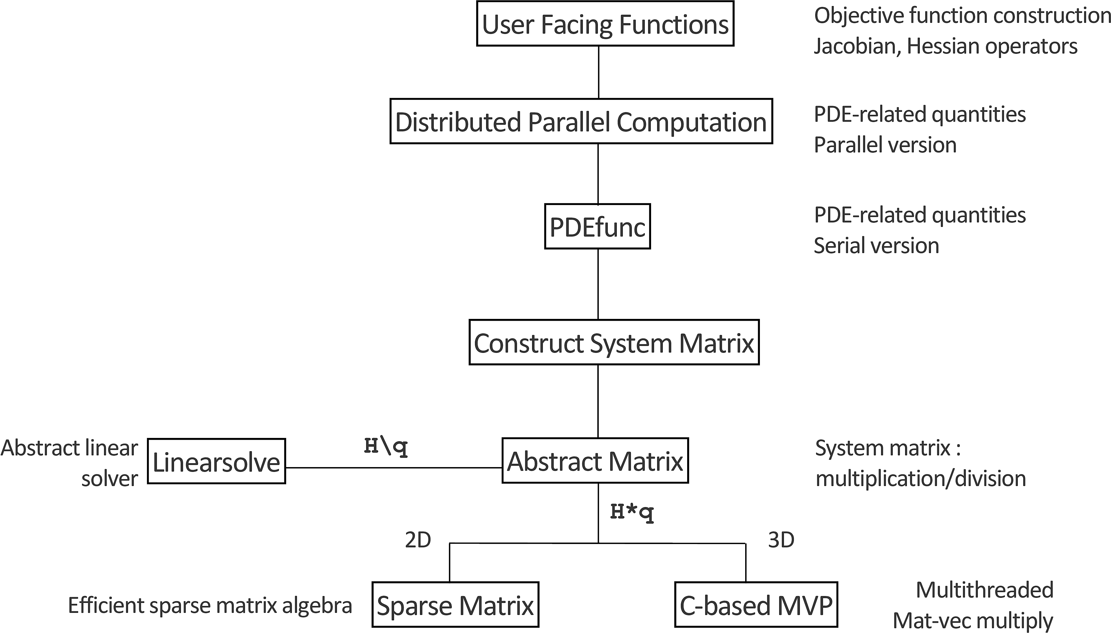
We decouple the various components of the inverse problem context by using an appropriate software hierarchy, which manages complexity level-by-level and will allow us to test components individually to ensure their correctness and efficiency, as shown in Figure 1. Each level of the hierarchy is responsible for a specific set of procedural requirements and defers the details of lower level computations to lower levels in the hierarchy.
At the topmost level, our user-facing functions are responsible for constructing a misfit function suitable for black-box optimization routines such as LBFGS or Newton-type methods (D. C. Liu and Nocedal, 1989; Zhu et al., 1997; Grippo et al., 1989). This procedure consists of
- handling subsampling of sources/frequencies for the distributed data volume
- coarsening the model, if required (for low frequency 3D problems)
- constructing the function interface that returns the objective, gradient, and requested Hessian at the current point.
For the Helmholtz case in particular, coarsening the model allows us to keep the number of degrees of freedom to a minimum, in line with the requirements of the discretization. In order to accommodate stochastic optimization algorithsm, we provide an option for a batch mode interface, which allows the objective function to take in as input both a model vector and a set of source-frequency indices. This option allows either the user or the outer stochastic algorithm to dynamically specify which sources and frequencies should be computed at a given time. This auxiliary information is passed along to lower layers of the hierarchy. Additionally, we provide methods to construct the Jacobian, Gauss-Newton, and Full Hessian as SPOT operators. For instance, when writing \(\text{Hess}*v\) as in a linear solver, Matlab implicitly calls the lower level functions that actually solve the PDEs to compute this product, all the while never forming the matrix explicitly. Information hiding in this fashion allows us to use existing linear solver codes written in Matlab (Conjugate Gradient, MINRES, etc.) to solve the resulting systems. For the parameter inversion problem, the user can choose to have either the Gauss-Newton or full Hessian operators returned at the current point.
Lower down the hierarchy, we have our PDEfunc layer. This function is responsible for computing the quantities of interest, i.e., the objective value, gradient, Hessian or Gauss-Newton Hessian matrix-vector product, forward modelling operator, or linearized forward modelling operator and its adjoint. At this stage in the hierarchy, we are concerned with ‘assembling’ the relevant quantities based on PDE solutions in to their proper configurations, rather than how exactly to obtain such solutions, i.e., we implement the formulas in Table 1. Here the PDE system matrix is a SPOT operator that has methods for performing matrix-vector products and matrix-vector divisions, which contains information about the particular stencil to use as well as which linear solvers and preconditioners to call. When dealing with 2D problems, this SPOT operator is merely a shallow wrapper around a sparse matrix object and contains its sparse factorization, which helps speed up solving PDEs with multiple right hand sides. In order to discretize the delta source function, we use Kaiser-windowed sinc interpolation (Hicks, 2002). At this level in the hierarchy, our code is not sensitive to the discretization or even the particular PDE we are solving, as we demonstrate in Section (#expoisson) with a finite volume discretization of the Poisson equation. To illustrate how closely our code resembles the underlying mathematics, we include a short snippet of code from our PDEfunc below in Figure 1.
% Set up interpolation operators
% Source grid -> Computational Grid
Ps = opInterp('sinc',model.xsrc,xt,model.ysrc,yt,model.zsrc,zt);
% Computational grid -> Receiver grid
Pr = opInterp('sinc',model.xrec,xt,model.yrec,yt,model.zrec,zt)';
% Sum along sources dimension
sum_srcs = @(x) to_phys*sum(real(x),2);
% Get Helmholtz operator, computational grid struct, its derivative
[Hk,comp_grid,T,DT_adj] = discrete_pde_system(v,model,freq(k),params);
U = H \ Q;
switch func
 case OBJ
    [phi,dphi] = misfit(Pr*U,getData(Dobs,data_idx),current_src_idx,freq_idx);
    f = f + phi;
    if nargout >= 2
        V = H' \ ( -Pr'* dphi);
        g = g + sum_srcs(T(U)'*V);
    end

 case FORW_MODEL
    output(:,data_idx) = Pr*U;

 case JACOB_FORW
    dm = to_comp*vec(input);
    dU = H\(-T(U)*dm);
    output(:,data_idx) = Pr*dU;

 case JACOB_ADJ
    V = H'\( -Pr'* input(:,data_idx) );
    output = output + sum_srcs(T(U)'*V);

 case HESS_GN
    dm = to_comp*vec(input);
    dU = H\(-T(U)*dm);
    dU = H'\(-Pr'*Pr*dU);
    output = output + sum_srcs(T(U)*dU);

 case HESS
    dm = to_comp*vec(input);
    [~,dphi,d2phi] = misfit(Pr*U,getData(Dobs,data_idx),current_src_idx,freq_idx);
    dU = H\(-T(U)*dm);
    V = H'\(-Pr'*dphi);
    dV = H'\(-T(V)*dm - Pr'* reshape(d2phi*vec(Pr*dU),nrec,size(U,2)));
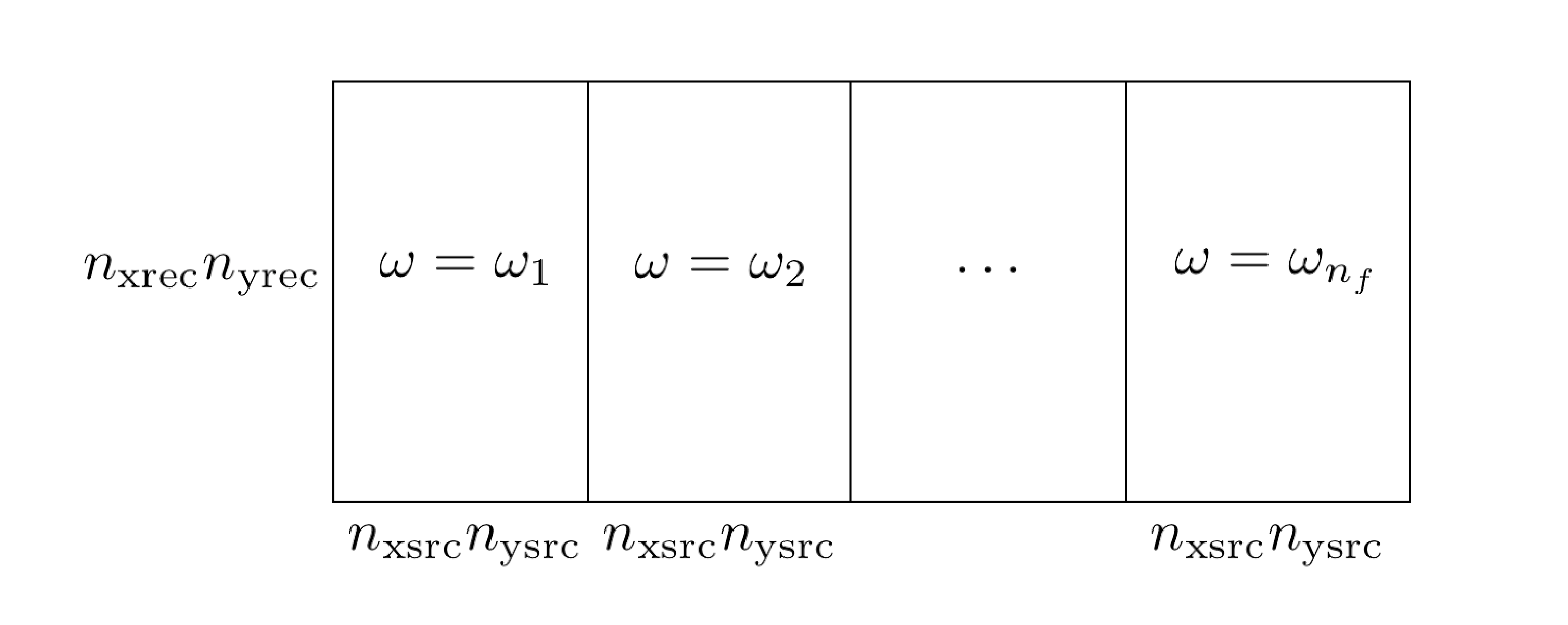
output = output + sum_srcs(DT_adj(U,dm,dU)*V + T(U)*dV);PDEfunc.In our parallel distribution layer, we compute the result of PDEfunc in an embarrassingly parallel manner by distributing over sources and frequencies and summing the results computed across various Matlab workers. This distribution scheme uses Matlab’s Parallel Toolbox, which is capable of Single Program Multiple Data (SPMD) computations that allow us to call PDEfunc identically on different subsets of source/frequency indices. The data is distributed as in Figure (2). The results of the local worker computations are then summed together (for the objective, gradient, adjoint-forward modelling, Hessian-vector products) or assembled in to a distributed vector (forward modelling, linearized forward modelling). Despite the ease of use in performing these parallel computations, the parallelism of Matlab is not fault-tolerant, in that if a single worker or process crashes at any point in computing a local value with PDEfunc, the parent calling function aborts as well. In a large-scale computing environment, this sort of behaviour is unreliable and therefore we recommend swapping out this ‘always-on’ approach with a more resilient model such as a map reduce paradigm. One possible implementation workaround is to measure the elapsed time of each worker, assuming that the work is distributed evenly. In the event that a worker times out, one can simply omit the results of that worker and sum together the remaining function and gradient values. In some sense, one can account for random machine failure or disconnection by considering it another source of stochasticity in an outer-level stochastic optimization algorithm.
Further down the hierarchy, we construct the system matrix for the PDE in the following manner. As input, we require the current parameters \(m\), information about the geometry of the problem (current frequency, grid points and spacing, options for number of PML points), as well as performance and linear solver options (number of threads, which solver/preconditioner to use, etc.). This function also extends the medium parameters to the PML extended domain, if required. The resulting outputs are a SPOT operator of the Helmholtz matrix, which has suitable routines for performing matrix-vector multiplications and divisions, a struct detailing the geometry of the pml-extended problem, and the mappings \(T\) and \(DT^*[\delta m]\) from Table (1). It is in this function that we also construct the user-specified preconditioner for inverting the Helmholtz (or other system) matrix.
The actual operator that is returned by this method is a SPOT operator that performs matrix-vector products and matrix-vector divisions with the underlying matrix, which may take a variety of forms. In the 2D regime, we can afford to explicitly construct the sparse matrix and we utilize the efficient sparse linear algebra routines in Matlab for solving the resulting linear system. In this case, we implement the 9pt optimal discretization of (Z. Chen et al., 2013), which fixes the problems associated to the 9pt discretization of (Jo et al., 1996), and use the sparse LU decomposition built in to Matlab for inverting the system. These factors are computed at the initialization of the system matrix and are reused across multiple sources. In the 3D regime, we implement a stencil-based matrix-vector product (i.e., one with coefficients constructed on the fly) written in C++, using the compact 27-pt stencil of (Operto et al., 2007) along with its adjoint and derivative. The stencil-based approach allows us to avoid having to keep, in this case, 27 additional vectors of the size of the PML-extended model in memory. This implementation is multi-threaded along the \(z-\)axis using OpenMP and is the only ‘low-level’ component in this software framework, geared towards high performance. Since this primitive operation is used throughout the inverse problem framework, in particular for the iterative matrix-vector division, any performance improvements made to this code will propagate throughout the entire codebase. Likewise, if a ‘better’ discretization of the PDE becomes available, it can be easily integrated in to the software framework by swapping out the existing function at this stage, without modifying the rest of the codebase. When it is constructed, this SPOT operator also contains all of the auxiliary information necessary for performing matrix-vector products (either the matrix itself, for 2D, or the PML-extended model vector and geometry information, for 3D) as well as for matrix-vector divisions (options for the linear solver, preconditioner function handle, etc.).
We allow the user access to multiplication, division, and other matrix operations like Jacobi and Kaczmarz sweeps through a unified interface, irrespective of whether the underlying matrix is represented explicitly or implicitly via function calls. For the explicit matrix case, we have implemented such basic operations in Matlab. When the matrix is represented implicitly, these operations are presented by a standard function handle or a ‘FuncObj’ object, the latter of which mirrors the Functor paradigm in C++. In the Matlab case, the ‘FuncObj’ stores a reference to a function handle, as well as a list of arguments. These arguments can be partially specialized upon construction, whereby only some of the arguments are specified at first. Later on when they are invoked, the remainder of their arguments are passed along to the function. In a sense, they implement the same functionality of anonymous functions in Matlab without the variable references to the surrounding workspace, which can be costly when passing around vectors of size \(N^3\) and without the variable scoping issues inherent in Matlab. We use this construction to specify the various functions that implement the specific operations for the specific stencils. Through this delegation pattern, we present a unified interface to the PDE system matrix irrespective of the underlying stencil or even PDE in question.
When writing u = H\q for this abstract matrix object \(H\), Matlab calls the ‘linsolve’ function, which delegates the task of solving the linear system to a user-specified solver. This function sets up all of the necessary preamble for solving the linear system with a particular method and preconditioner. Certain methods such as the row-based Carp-CG method, introduced in (Gordon and Gordon, 2010) and applied to seismic problems in (Leeuwen and Herrmann, 2014), require initial setup, which is performed here. This construction allows us to easily reuse the idea of ‘solving a linear system with a specific method’ in setting up the multi-level preconditioner of the next section, which reduces the overall code complexity since the multigrid smoothers themselves can be described in this way.
In order to manage the myriad of options available for computing with these functions, we distinguish between two classes of options and use two separate objects to manage them. ‘LinSolveOpts’ is responsible for containing information about solving a given linear system, i.e., which solver to use, how many inner/outer iterations to perform, relative residual tolerance, and preconditioner. ‘PDEopts’ contains all of the other information that is pertinent to PDEfunc (e.g., how many fields to compute at a time, type of interpolation operators to use for sources/receivers, etc.) as well as propagating the options available for the PDE discretization (e.g., stencil to use, number of PML points to extend the model, etc.).
Extensions
This framework is flexible enough for us to integrate additional models beyond the standard adjoint-state problem. We outline two such extensions below.
Penalty Method
Given the highly oscillatory nature of the forward modelling operator, due to the presence of the inverse Helmholtz matrix \(H(m)^{-1}q\), one can also consider relaxing the exact constraint \(H(m)u(m)=q\) in to an unconstrained and penalized form of the problem. This is the so-called Waveform Reconstruction Inversion approach (Leeuwen et al., 2014), which results in the following problem, for a least-squares data-misfit penalty, \[ \begin{equation} \min_m = \dfrac{1}{2}\|Pu(m)-d\|_2^2 + \dfrac{\lambda^2}{2} \|H(m)u(m) - q\|_2^2 \label{wri} \end{equation} \] where \(u(m)\) solves the least-squares system \[ \begin{equation} u(m) = \argmin_{u} \dfrac{1}{2} \|Pu - d\|_2^2 + \dfrac{\lambda^2}{2} \|H(m)u-q\|_2^2. \label{wrifieldeq} \end{equation} \] The notion of variable projection (A. Y. Aravkin and Van Leeuwen, 2012) underlines this method, whereby the field \(u\) is projected out of the problem by solving \(\eqref{wrifieldeq}\) for each fixed \(m\). We perform the same derivations for problem \(\eqref{wri}\) in Appendix (#wrideriv). Given the close relationship between the two methods, the penalty method formulation is integrated into the same function as our FWI code, with a simple flag to change between the two computational modes. The full expressions for the gradient, Hessian, and Gauss-Newton Hessian of WRI are outlined in Appendix B.
2.5D
For a 3D velocity model that is invariant with respect to one dimension, i.e., \(v(x,y,z) = h(x,z) \text{ for all } y\), so \(m(x,y,z) = \omega^2 g(x,z) \) for \(g(x,z) = \dfrac{1}{h^2(x,z)}\), we can take a Fourier transform in the y-coordinate of \(\eqref{helmholtz}\) to obtain \[ \begin{equation*} (\partial_x^2 + \partial_z^2 + \omega^2 g(x,z) - k^2_{y})\hat{u}(x,k_y,z) = S(\omega)\delta(x-x_s)\delta(z-z_s)e^{-ik_y y_s}. \end{equation*} \] This so-called 2.5D modeling/inversion allows us to mimic the physical behaviour of 3D wavefield propagation (e.g., \(1/r\) amplitude decay vs \(1/r^{1/2}\) decay in 2D, point sources instead of line sources, etc.) without the full computational burden of solving the 3D Helmholtz equation (Song and Williamson, 1995). We solve a series of 2D problems instead, as follows.
Multiplying both sides by \(e^{ik_y y_s}\) and setting \(\tilde{u}_{k_y}(x,z) = e^{ik_yy_s} \hat{u}(x,k_y,z)\), we have that, for each fixed \(k_y\), \(\tilde{u}_{k_y}\) is the solution of \(H(k_y)\tilde{u}_{k_y}=S(\omega)\delta(x-x_s)\delta(z-z_s)\) where \(H(k_y) = (\partial_x^2 + \partial_z^2 + \omega^2 g(x,z) - k^2_{y})\).
We can recover \(u(x,y,z)\) by writing \[ \begin{equation*} \begin{aligned} u(x,y,z) &= \dfrac{1}{2\pi}\int_{-\infty}^{\infty} \hat{u}_{k_y}(x,z) e^{ik_y y} dk_y \\ &= \dfrac{1}{2\pi}\int_{-\infty}^{\infty} \tilde{u}_{k_y}(x,z) e^{ik_y (y-y_s)} dk_y \\ &= \dfrac{1}{\pi}\int_0^{\infty} \tilde{u}_{k_y}(x,z) \cos(k_y (y-y_s)) dk_y \\ &= \dfrac{1}{\pi}\int_0^{k_{nyq}} \tilde{u}_{k_y}(x,z) \cos(k_y (y-y_s)) dk_y. \end{aligned} \end{equation*} \] Here the third line follows from the symmetry between \(k_y\) and \(-k_y\) and the fourth line restricts the integral to the Nyquist frequency given by the sampling in \(y\), namely \(k_{nyq} = \frac{\pi}{\Delta y}\) (Song and Williamson, 1995). One can further restrict the range of frequencies to \([0,p\cdot k_c]\) where \(k_c = \frac{\omega}{\min_{x,z}v(x,z)}\) is the so-called critical frequency and \(p \ge 1, p \approx 1.\) In this case, waves corresponding to a frequency much higher than that of \(k_c\) do not contribute significantly to the solution. By evaluating this integral with, say, a Gauss-Legendre quadrature, the resulting wavefield can be expressed as \[ \begin{equation*} u(x,y,z) = \sum_{i=1}^{N} w_i \tilde{u}_{k^i_y}(x,z), \end{equation*} \] which is a sum of 2D wavefields. This translates in to operations such as computing the Jacobian or Hessian having the same sum structure and allows us to incorporate 2.5D modeling and inversion easily in to the resulting software framework.
Multi-level Recursive Preconditioner for the Helmholtz Equation
Owing to the PML layer and indefiniteness of the underlying PDE system for sufficiently high frequencies, the Helmholtz system matrix is complex-valued, non-Hermitian, indefinite, and therefore challenging to solve using Krylov methods without adequate preconditioning. There have been a variety of ideas proposed to precondition the Helmholtz system, including multigrid methods (Stolk et al., 2014), methods inverting the shifted Laplacian system (Riyanti et al., 2007; Plessix, 2007; Erlangga et al., 2004), sweeping preconditioners (B. Engquist and Ying, 2011; F. Liu and Ying, 2015, 2016; Poulson et al., 2013), domain decomposition methods (Stolk, 2013, 2016; Boubendir et al., 2012; Gander and Zhang, 2013), and Kaczmarz sweeps (Leeuwen et al., 2012), among others. These methods have varying degrees of applicability in this framework. Some methods such as the sweeping preconditioners rely on having explicit representations of the Helmholtz matrix and keeping track of dense LU factors on multiple subdomains. Their memory requirements are quite steep as a result and they require a significant amount of bookkeeping to program correctly, in addition to their large setup time, which is prohibitive in inversion algorithms where the velocity is being updated. Many of these existing methods also make stringent demands of the number of points per wavelength \(N_{\text{ppw}}\) needed to succeed, in the realm of \(10\) to \(15\), which results in prohibitively large system matrices for the purposes of inversion. As the standard 7pt discretization requires a high \(N_{\text{ppw}}\) in order to adequately resolve the solutions of the phases (Operto et al., 2007), this results in a large computational burden as the system size increases.
Our aim in this section is to develop a preconditioner that is scalable, in that it uses the multi-threading resources on a given computational node, easy to program, matrix-free, without requiring access to the entries of the system matrix, and leads to a reasonably low number of outer Krylov iterations. It is more important to have a larger number of sources distributed to multiple nodes rather than using multiple nodes solving a single problem when working in a computational environment where there is a nonzero probability of node failure.
We follow the development of the preconditioners in (Calandra et al., 2013; Lago and Herrmann, 2015), which uses a multigrid approach to preconditioning the Helmholtz equation. The preconditioner in (Calandra et al., 2013) approximates a solution to \(\eqref{mainprob}\) with a two-level preconditioner. Specifically, we start with a standard multigrid V-cycle (Briggs et al., 2000) as described in Figure (1). The smoothing operator aims to reduce the amplitude of the low frequency components of the solution error, while the restriction and prolongation operators. For an extensive overview of the multigrid method, we refer the reader to (Briggs et al., 2000). We use linear interpolation as the prolongation operator and its adjoint as for restriction, although other choices are possible (De Zeeuw, 1990).
V-cycle to solve \(H_f x_f = b_f\) on the fine scale
Input: Current estimate of the fine-scale solution \(x_f\)
Smooth the current solution using a particular smoother (Jacobi, CG, etc.) to produce \(\tilde{x}_f\)
Compute the residual \(r_f = b_f - A_f \tilde{x}_f\)
Restrict the residual, right hand side to the coarse level \(r_c = Rr_f\), \(b_c = Rb_f\)
Approximately solve \(H_c x_c = r_c\)
Interpolate the coarse-scale solution to the fine-grid, add it back to \(\tilde{x}_f\), \(\tilde{x}_f \leftarrow x_f + Px_c\)
Smooth the current solution using a particular smoother (Jacobi, CG, etc.) to produce \(\tilde{x}_f\)
Output: \(\tilde{x}_f\)
In the original work, the coarse-scale problem is solved with GMRES preconditioned by the approximate inverse of the shifted Laplacian system, which is applied via another V-cycle procedure. In this case, we note that the coarse-scale problem is merely an instance of the original problem and since we apply the V-cycle in (1) to precondition the original problem, we can recursively apply the same method to precondition the coarse-scale problem as well. This process cannot be iterated beyond two-levels typically because of the minimum grid points per wavelength sampling requirements for wave phenomena (Cohen, 2013).
Unfortunately as-is, the method of (Calandra et al., 2013) was only designed with the standard, 7-pt stencil in mind, rather than the more robust 27-pt stencil of (Operto et al., 2007). The work of (Lago and Herrmann, 2015) demonstrates that a straightforward application of the previous preconditioner to the new stencil fails to converge. The authors attempt to extend these ideas to this new stencil by replacing the Jacobi iterations with the Carp-CG algorithm (Gordon and Gordon, 2010), which acts as a smoother in its own right. For realistically sized problems, this method performs poorly as the Carp-CG method is inherently sequential and attempts to parallelize it result in degraded convergence performance (Gordon and Gordon, 2010), in particular when implemented in a stencil-based environment. As such, we propose to reuse the existing fast matrix-vector kernels we have developed thus far and set our smoother to be GMRES (Saad and Schultz, 1986) with an identity preconditioner. Our coarse level solver is FGMRES (Saad, 1993), which allows us to use our nonlinear, iteration-varying preconditioner. Compared to our reference stencil-based Carp sweep implementation in C, a single-threaded matrix-vector multiplication is 30 times faster. In the context of preconditioning linear systems, this means that unless the convergence rate of the Carp sweeps are \(30/k_s\) faster than the GMRES-based smoothers, we should stick to the faster kernel for our problems. Furthermore, we observed experimentally in testing that using a shifted Laplacian preconditioner, as in (Calandra et al., 2013; Lago and Herrmann, 2015) on the second level caused an increase in the number of outer iterations, slows down convergence. As such, we have replaced preconditioning the shifted Laplacian system by preconditioning the Helmholtz itself, solved with FGMRES, which results in much faster convergence.
A diagram of the full algorithm, which we denote \(ML-GMRES\), is depicted in Figure (3). This algorithm is matrix-free, in that we do not have to construct any of the intermediate matrices explicitly and instead merely compute matrix-vector products, which will allow us to apply this method to large systems.

We experimentally study the convergence behaviour of this preconditioner on a 3D constant velocity model and leave a theoretical study of ML-GMRES for future work. By fixing the preconditioner memory vector to be \((k_{s,o},k_{s,i},k_{c,o},k_{c,i}) = (3,5,3,5)\), we can study the performance of the preconditioner as we vary the number of wavelengths in each direction, denoted \(n_{\lambda}\), as well as the number of points per wavelength, denoted \(n_{\text{ppw}}\). For a fixed domain, as the former quantity increases, the frequency increases while as the latter quantity increases, the grid sampling decreases. As an aside, we prefer to parametrize our problems in this manner as these quantities are independent of the scaling of the domain, velocity, and frequency, which are often obscured in preconditioner examples in research. These two quantities, \(n_{\lambda}\) and \(n_{\text{ppw}}\), on the other hand, are explicitly given parameters and comparable across experiments. We append our model with a number of PML points equal to one wavelength on each side. Using 5 threads per matrix-vector multiply, we use FGMRES with 5 inner iterations as our outer solver, solve the system to a relative residual of \(10^{-6}\). The results are displayed in Table (3).
| \(n_{\lambda} / n_{\text{ppw}}\) | 6 | 8 | 10 |
|---|---|---|---|
| 5 | 2 (\(43^3\), 4.6) | 2 (\(57^3\), 6.9) | 2 (\(71^3\), 10.8) |
| 10 | 3 (\(73^3\), 28.9) | 2 (\(97^3\), 38.8) | 2 (\(121^3\), 76.8) |
| 25 | 8 (\(161^3\), 809) | 3 (\(217^3\), 615) | 3 (\(271^3\), 1009.8) |
| 40 | 11 (\(253^3\), 4545) | 3 (\(337^3\), 2795) | 3 (\(421^3\), 4747) |
| 50 | 15 (\(311^3\), 11789) | 3 (\(417^3\), 5741) | 3 (\(521^3\), 10373) |
We upper bound the memory usage of ML-GMRES as follows. We note that the FGMRES(\(k_o,k_i\)), GMRES(\(k_o,k_i\)) solvers, with \(k_o\) outer iterations and \(k_i\) inner iterations, store \(2k_i+6\) vectors and \(k_i+5\) vectors, respectively. In solving the discretized \(H(m)u = q\) with \(N = n^3\) complex-valued unknowns, we require \((2k_i+6)N\) memory for the outer FGMRES solver, \(2N\) for additional vectors in the V-cycle, in addition to \((k_{s,i}+5)N\) memory for the level-1 smoother, \((2k_{c,i}+6)(N/8)\) memory for the level-2 outer solver, \((k_{s,i}+5)(N/8)\) memory for the level-2 smoother, and \((k_{c,i}+5)(N/64)\) memory for the level-3 solver. The total peak memory of the entire solver is therefore \[ \begin{equation*} (2k_i+6)N + \max( (k_{s,i}+5)N, (2k_{c,i} + 6)(N/8) + \max((k_{s,i}+5)N/8 , (2k_{c,i}+6)N/64)) \end{equation*} \] Using the same memory settings as before, our preconditioner requires at most \(26\) vectors to be stored. Although the memory requirements of our preconditioner are seemingly large, they are approximately the same cost as storing the entire 27-pt stencil coefficients of \(H(m)\) explicitly and much smaller than the LU factors in (Table 1, (Operto et al., 2007)). The memory requirements of this preconditioner can of course be reduced by reducing \(k\), \(k_s\) or \(k_c\), at the expense of an increased computational time per wavefield solve. To compute the real world memory usage of this preconditioner, we consider a constant model problem with \(10\) wavelengths and a varying number of points per wavelength so that the total number of points, including the PML region, is fixed. In short, we are not changing the effective difficulty of the problem, but merely increase the oversampling factor to ensure that the convergence remains the same with increasing model size. The results in Table (4) indicate that ML-GMRES is performing slightly better than expected from a memory point of view and the computational time scaling is as expected.
| Grid Size | Time(s) | Peak memory (GB) | Number of vectors of size \(N\) |
|---|---|---|---|
| \(128^3\) | 46 | 0.61 | \(20N\) |
| \(256^3\) | 213 | 5.8 | \(23N\) |
| \(512^3\) | 1899 | 48.3 | \(24N\) |
Despite the strong empirical performance of this preconditioner, we note that performance tends to degrade as \(n_{\text{ppw}} < 8\), even though the 27-pt compact stencil is rated for \(n_{\text{ppw}} = 4\) in (Operto et al., 2007). Intuitively this makes sense as on the coarsest grid \(n_{\text{ppw}} < 2\), which is under the Nyquist limit, and leads to stagnating convergence. In our experience, this discrepancy did not disappear when using the shifted Laplacian preconditioner on the coarsest level. It remains to be seen how multigrid methods for the Helmholtz equation with \(n_{\text{ppw}} < 8\) will be developed in future research.
Numerical Examples
Validation
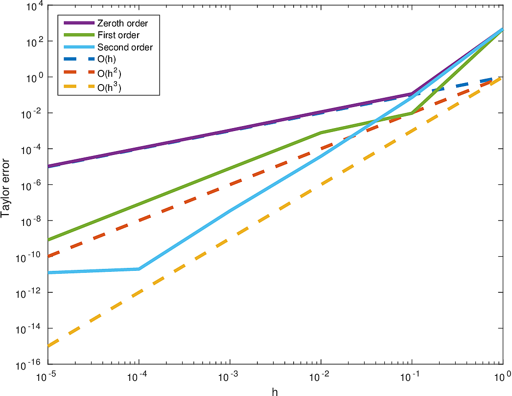
To verify the validity of this implementation, specifically that the code as implemented reflects the underlying mathematics, we ensure that the following tests pass. The Taylor error test stipulates that, for a sufficiently smooth multivariate function \(f(m)\) and an arbitrary perturbation \(\delta m\), we have that \[ \begin{equation*} \begin{aligned} &f(m+h\delta m) - f(m) &=&\; O(h)\\ &f(m+h\delta m) - f(m) - h \langle \nabla f(m), \delta m \rangle &=& \; O(h^2)\\ &f(m+h\delta m) - f(m) - h \langle \nabla f(m), \delta m \rangle - \dfrac{h^2}{2} \langle \delta m, \nabla^2 f(m)\delta m\rangle &=&\; O(h^3). \end{aligned} \end{equation*} \] We verify this behaviour numerically for the least-squares misfit \(f(m)\) and for a constant 3D velocity model \(m\) and a random perturbation \(\delta m\) by solving for our fields to a very high precision, in this case up to a relative residual of \(10^{-10}\). As shown in Figure (4), our numerical codes indeed pass this test, up until the point where \(h\) becomes so small that the numerical error in the field solutions dominates the other sources of error.
The adjoint test requires us to verify that, for the functions implementing the forward and adjoint matrix-vector products of a linear operator \(A\), we have, numerically, \[ \begin{equation*} \langle Ax, y \rangle = \langle x, A^H y \rangle, \end{equation*} \] for all vectors \(x,y\) of appropriate length. We suffice for testing this equality for randomly generated vectors \(x\) and \(y\), made complex if necessary. Owing to the presence of the PML extension operator for the Helmholtz equation, we set \(x\) and \(y\), if necessary, to be zero-filled in the PML-extension domain and along the boundary of the original domain. We display the results in Table (5).
| \(\langle Ax, y\rangle \) | \(\langle x, A^Hy\rangle\) | Relative difference | |
|---|---|---|---|
| Helmholtz | \(6.5755 - 5.2209 i \cdot 10^{0}\) | \(6.5755 - 5.2209 i \cdot 10^{0}\) | \(2.9004 \cdot 10^{-15}\) |
| Jacobian | \(1.0748 \cdot 10^{-1}\) | \(1.0748 \cdot 10^{-1}\) | \(1.9973 \cdot 10^{-9}\) |
| Hessian | \(-1.6465 \cdot 10^{-2}\) | \(-1.646 \cdot 10^{-2}\) | \(1.0478 \cdot 10^{-10}\) |
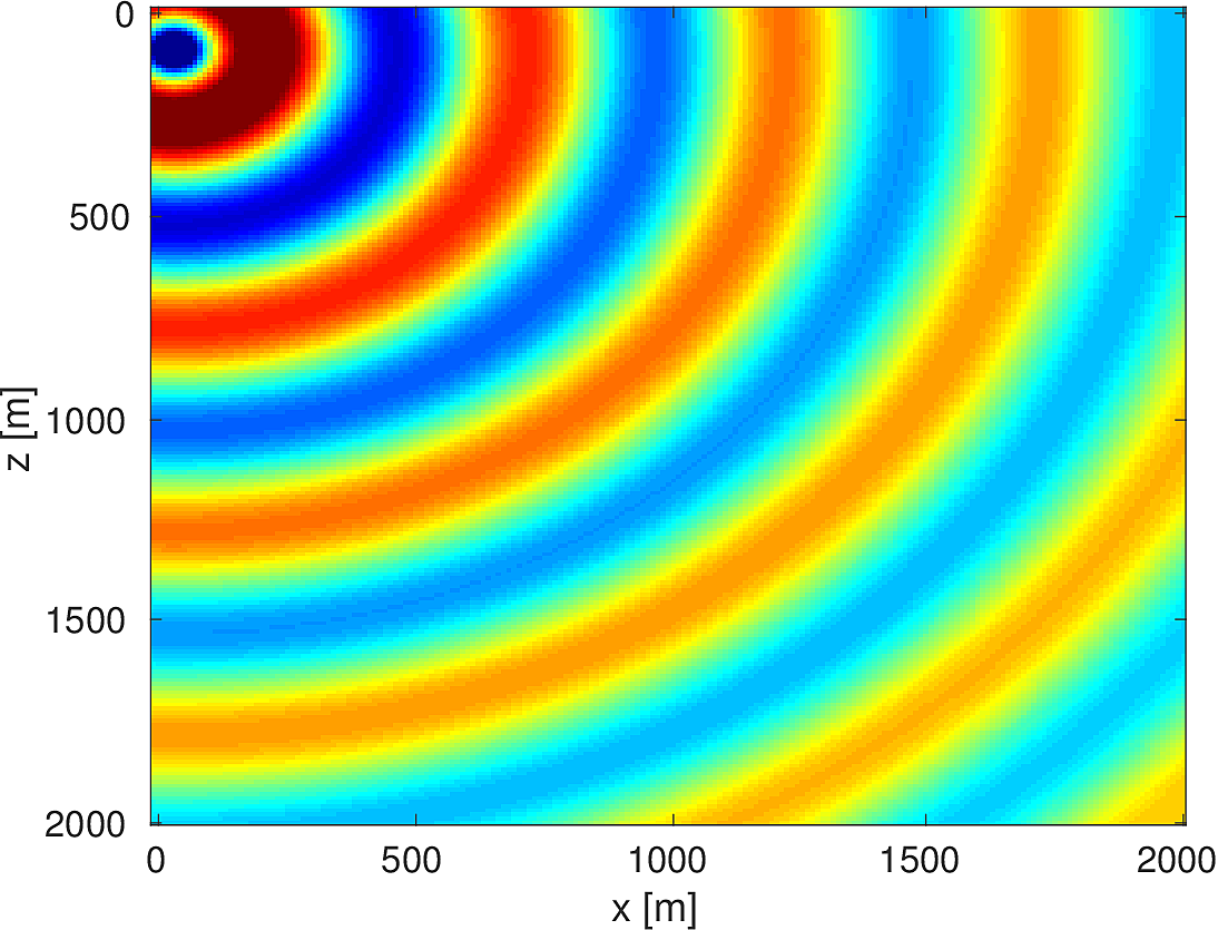
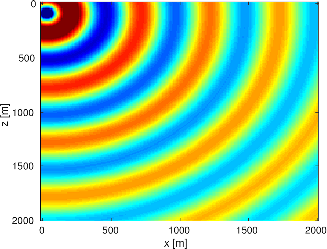
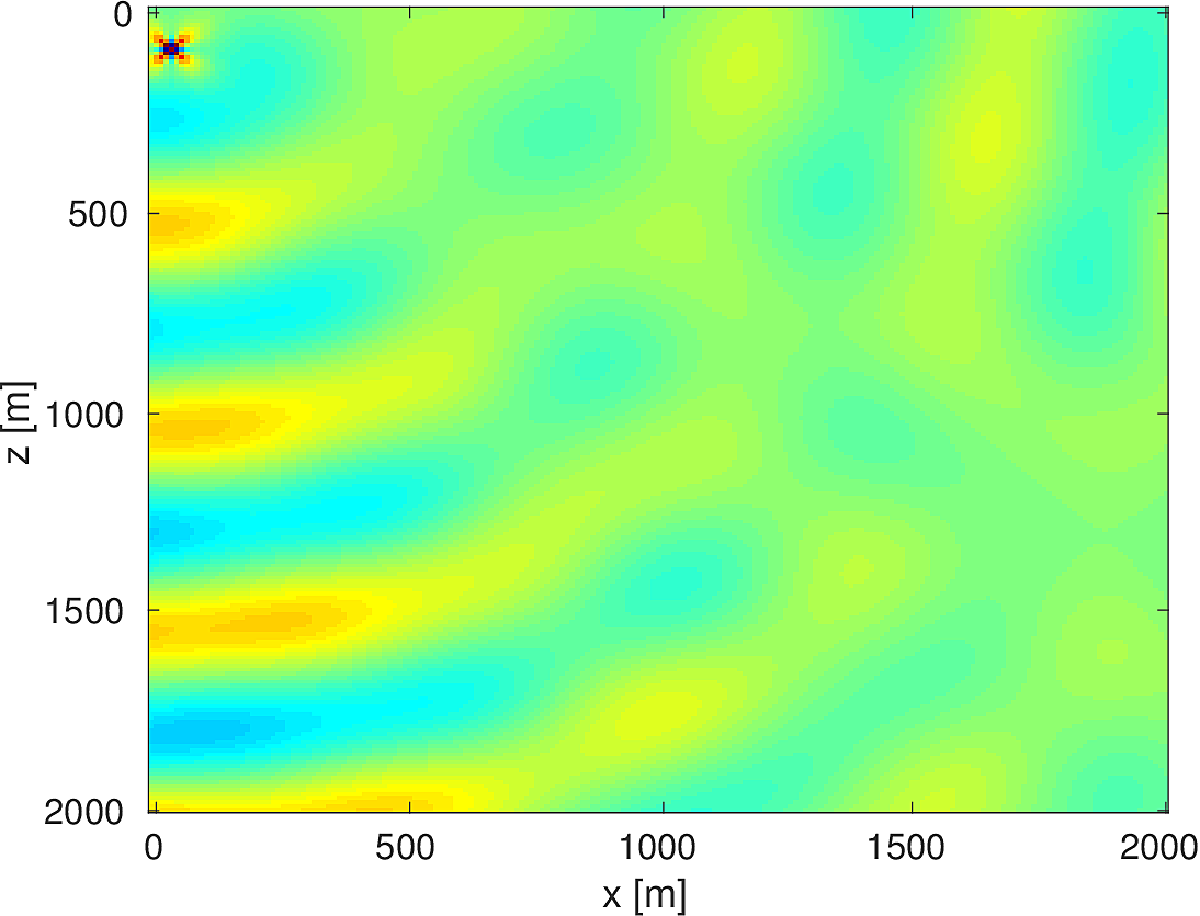
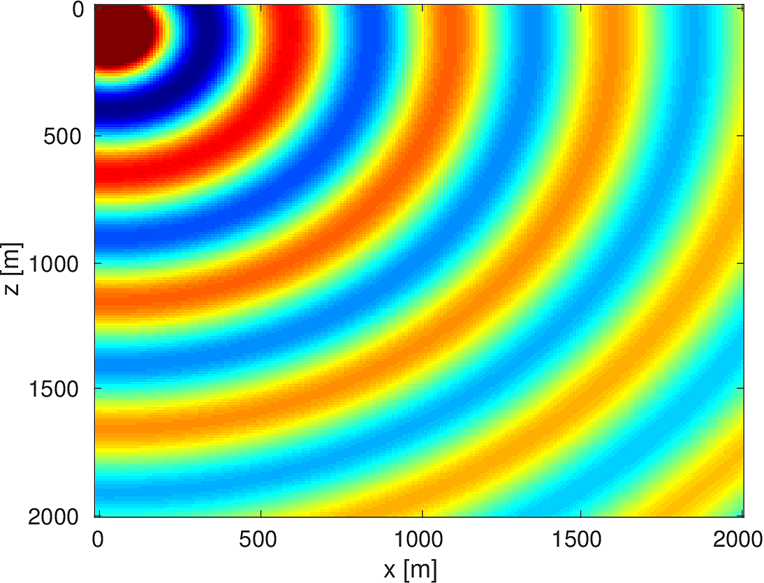
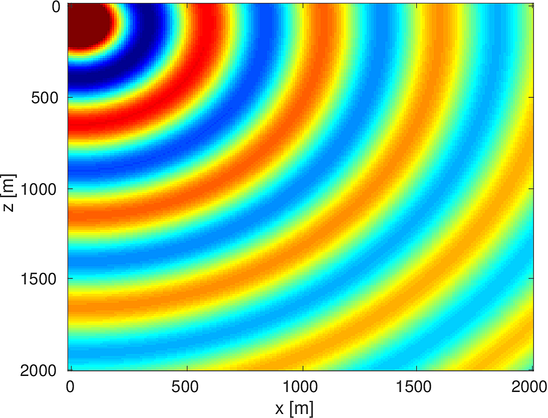
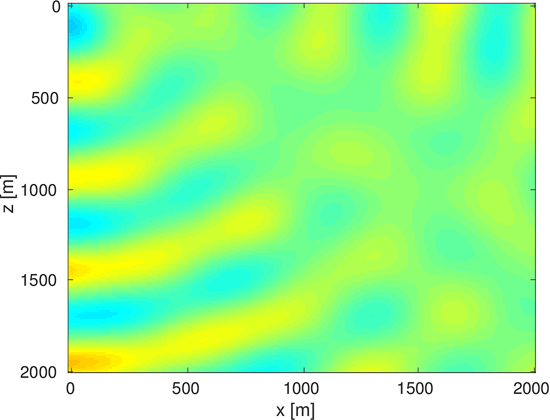
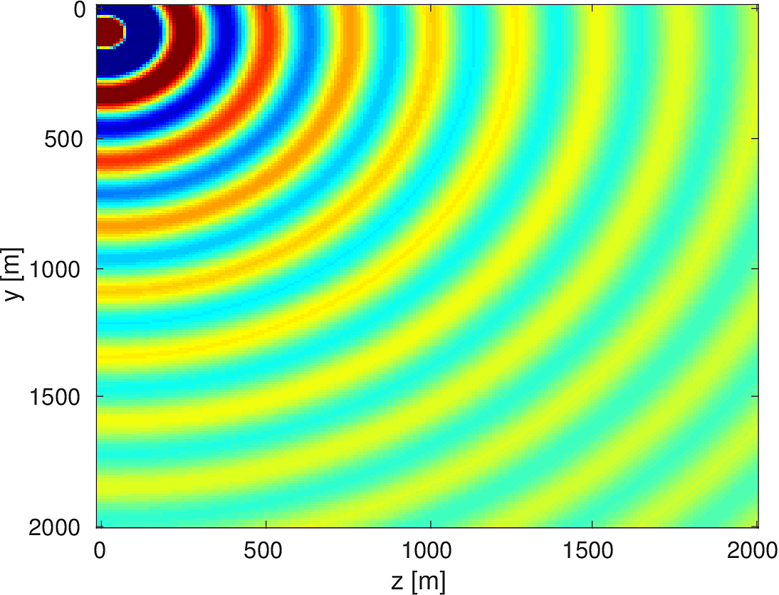
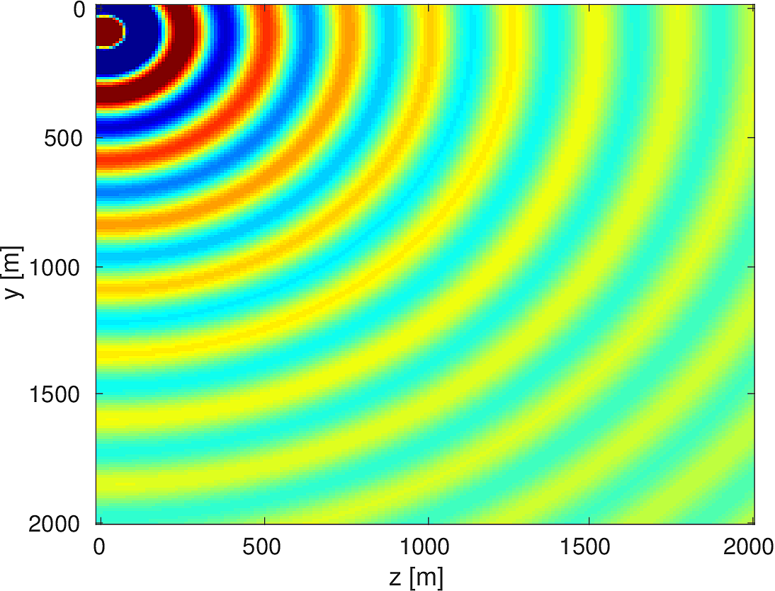
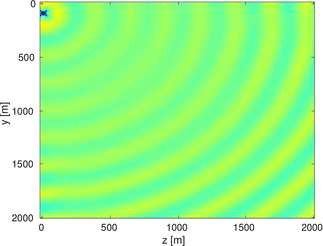
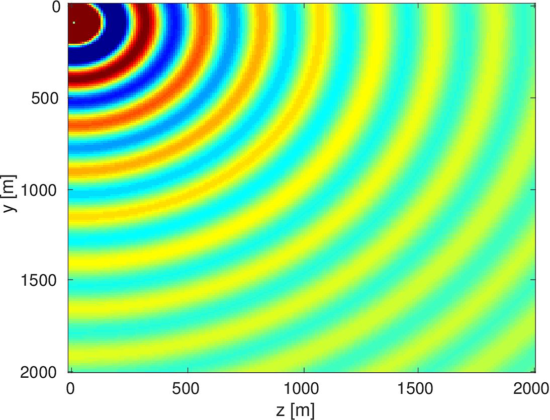
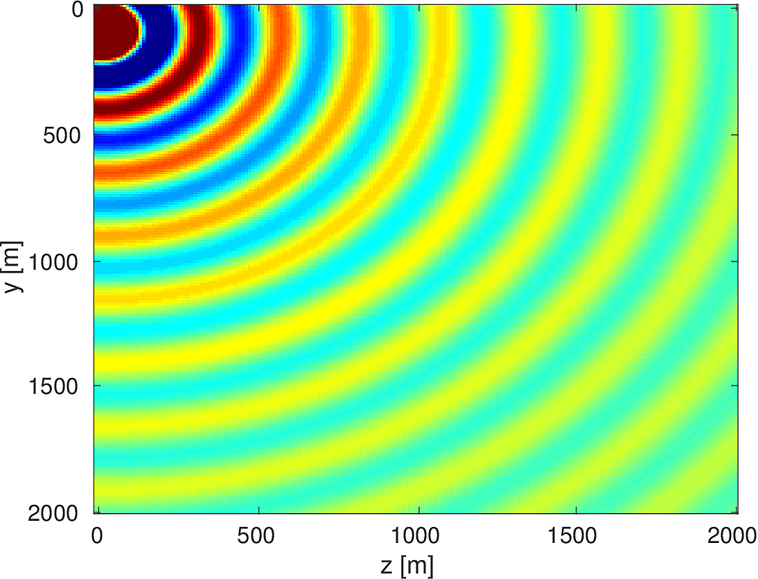
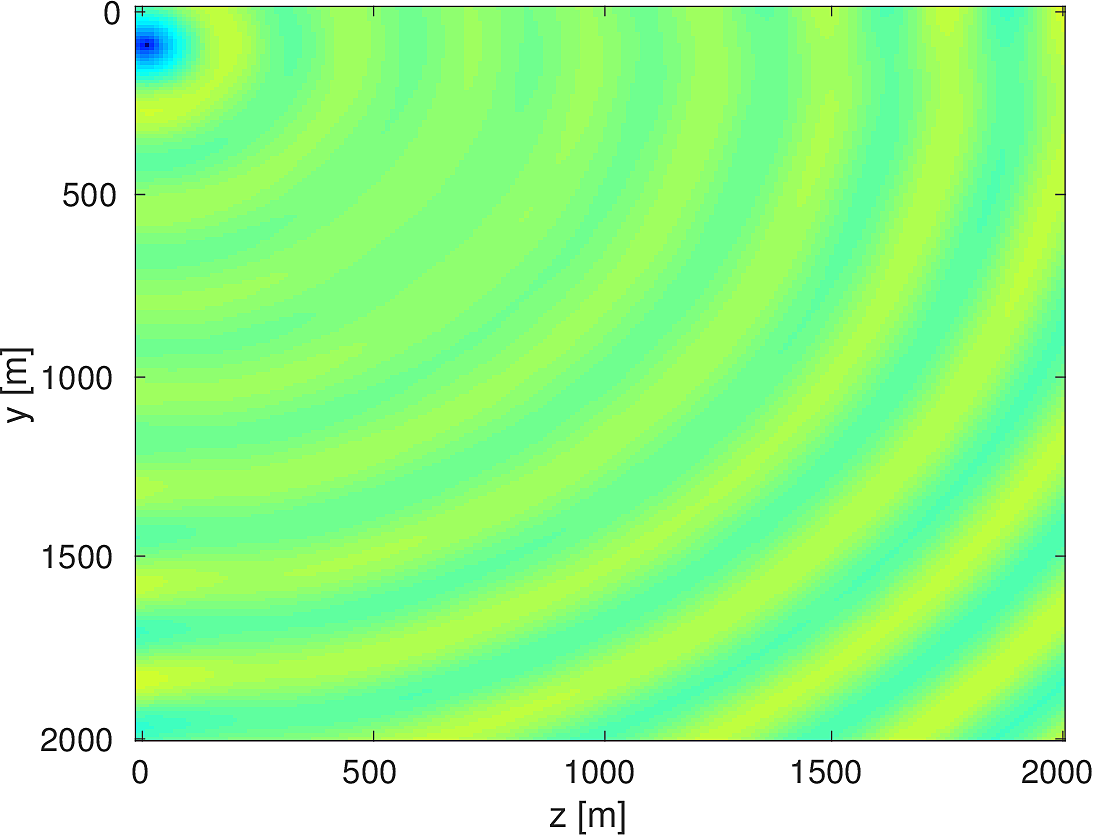
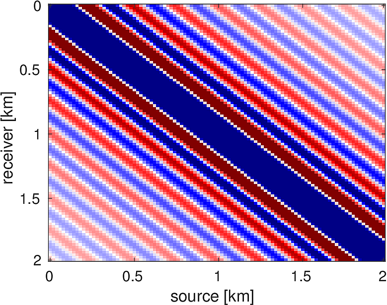
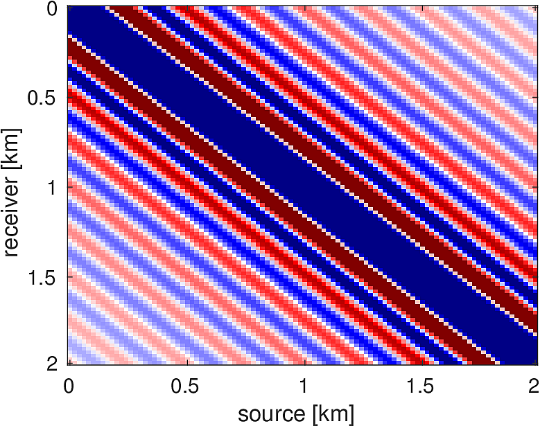
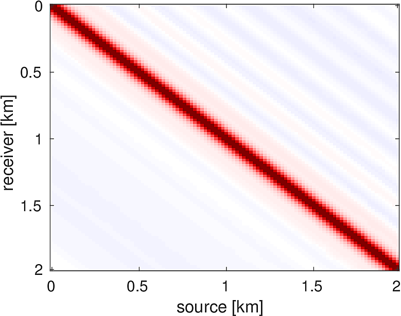
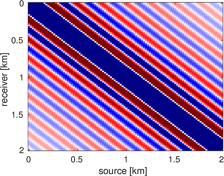
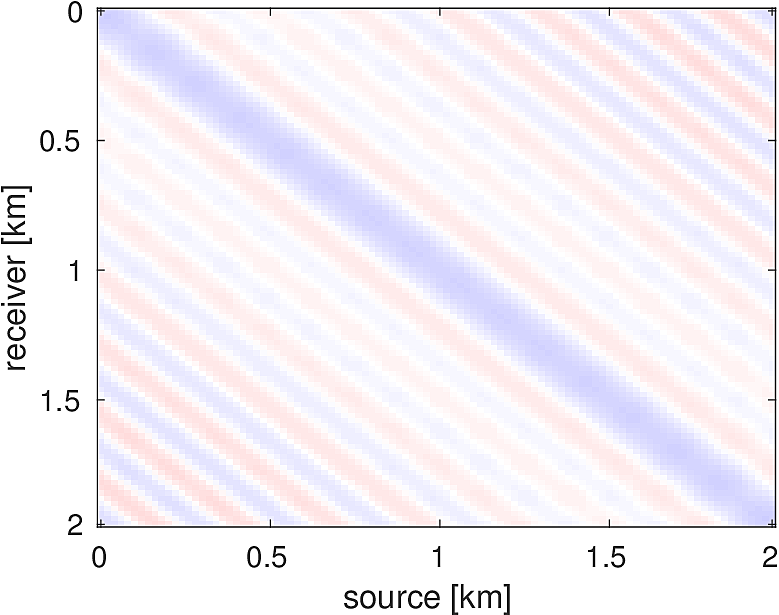
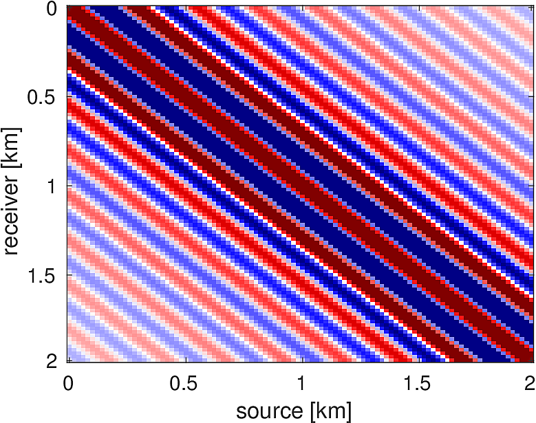
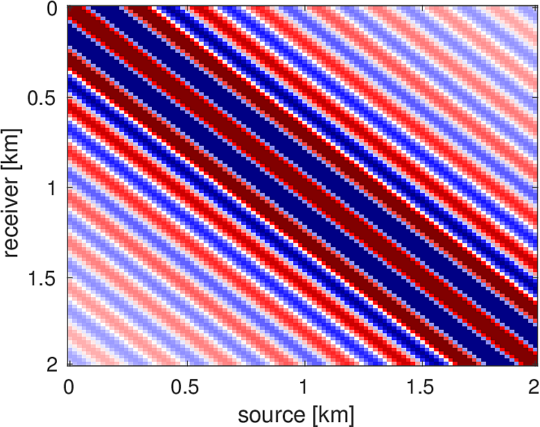
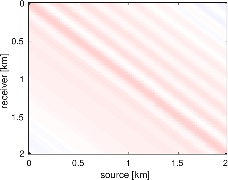
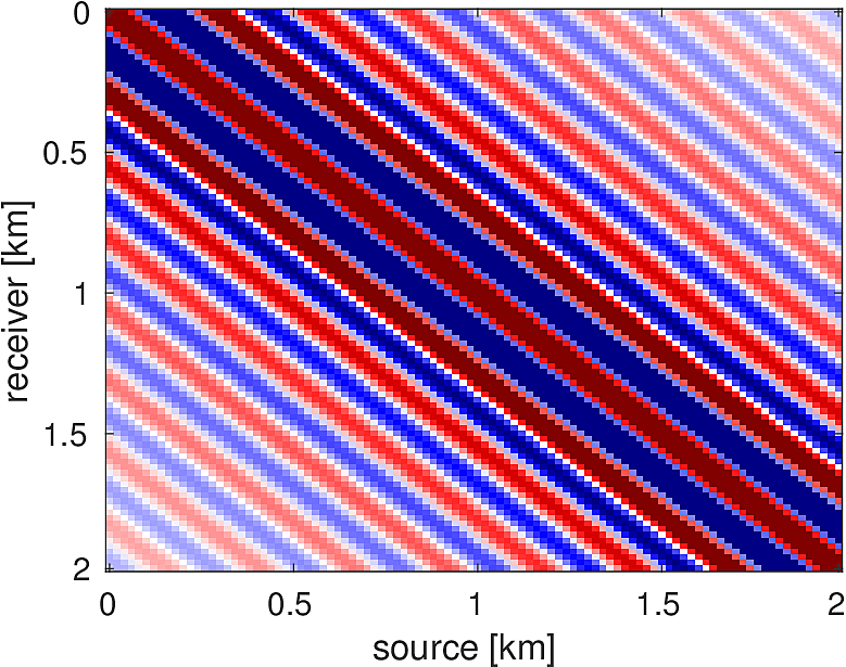
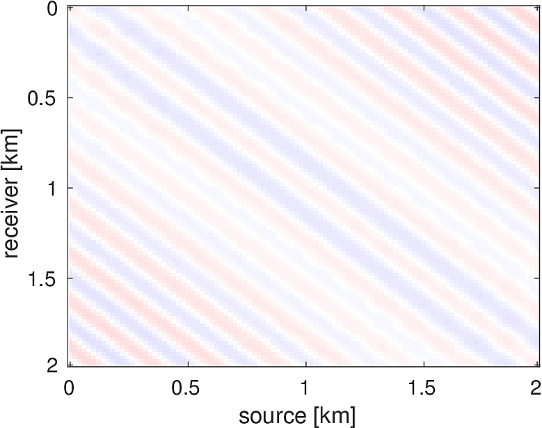
We also compare the computed solutions in a homogeneous medium to the corresponding analytic solutions in 2D and 3D, i.e., \[ \begin{equation*} \begin{aligned} G(x,x_s) &= -\dfrac{i}{4}H_0(\kappa \|x-x_s\|_2) & \quad \text{ in 2D }\\ G(x,x_s) &= \dfrac{e^{i \kappa \|x-x_s\|_2}}{4\pi \|x-x_s\|_2} & \quad \text{ in 3D } \end{aligned} \end{equation*} \] where \(\kappa = \dfrac{2\pi f}{v_0}\) is the wavenumber, \(f\) is the frequency in Hz, \(v_0\) is the velocity in \(m/s\), and \(H_0\) is the Bessel function of the third kind (the Hankel function). Figures (5, 6, 7) show the analytic and numerical results of computing solutions with the 2D, 3D, and 2.5D kernels, respectively. Here we see that the overall phase dispersion is low for the computed solutions, although we do incur a somewhat larger error around the source region as expected. The inclusion of the PML also prevents any visible artificial reflections from entering the solutions, as we can see from the (magnified) error plots.
Full Waveform Inversion
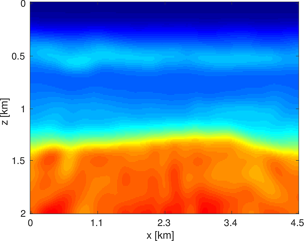
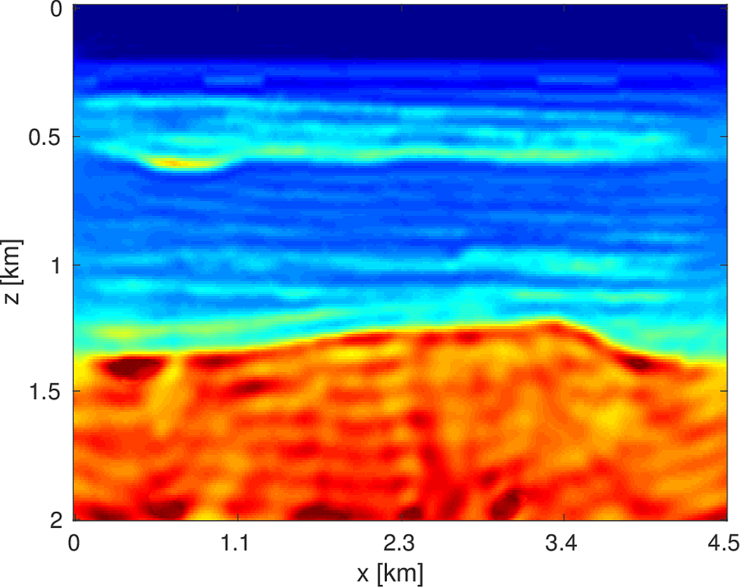
To demonstrate the effectiveness of our software environment, we perform a simple 2D FWI experiment on a 2D slice of the 3D BG Compass model. We generate data on this 2km x 4.5km model (discretized on a 10m grid) from 3Hz to 18Hz (in 1Hz increments) using our Helmholtz modeling kernel. Employing a frequency continuation strategy allows us to mitigate convergence issues associated with local minima (Virieux and Operto, 2009). That is to say, we partition the entire frequency spectrum \({3, 4, \dots, 18}\) in to overlapping subsets, select a subset at which to invert invert the model, and use the resulting model estimate as a warm-start for the next frequency band. In our case, we use frequency bands of size \(4\) with an overlap of \(2\) between bands. At each stage of the algorithm, we invert the model using \(20\) iterations of a box-constrained LBFGS algorithm from (M. W. Schmidt et al., 2009). An excerpt from the full script that produces this example is shown in Listing (2). The results of this algorithm are shown in Figure (8). As we are using a band with a low starting frequency (3Hz in this case), FWI is expected to perform well in this case, which we see that it does. Although an idealized experimental setup, our framework allows for the possibility of testing out algorithms that make use of higher starting frequencies, or use frequency extrapolation as in (Wang and Herrmann, 2016; Y. E. Li and Demanet, 2016), with minimal code changes.
% Set the initial model (a smoothed version of the true model)
mest = m0;
% Loop over subsets of frequencies
for j=1:size(freq_partition,1)
    % Extract the current frequencies at this batch
    fbatch = freq_partition(j,:);
    % Select only sources at this frequency batch
    srcfreqmask = false(nsrc,nfreq);
    srcfreqmask(:,fbatch) = true;
    params.srcfreqmask = srcfreqmask;
    % Construct objective function for these frequencies
    obj = misfit_setup(mest,Q,Dobs,model,params);
    % Call the box constrained LBFGS method
    mest = minConf_TMP(obj,mest,mlo,mhi,opts);
end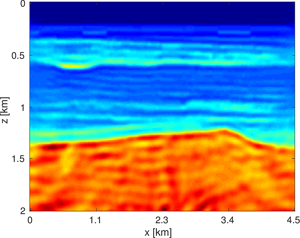
Sparsity Promoting Seismic Imaging
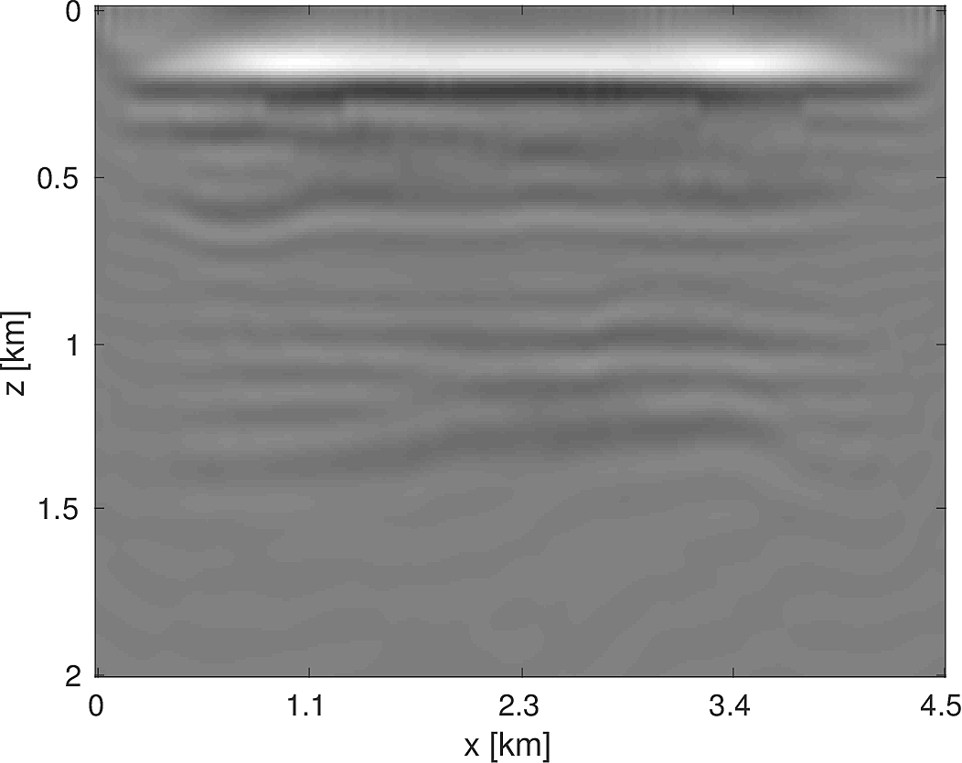
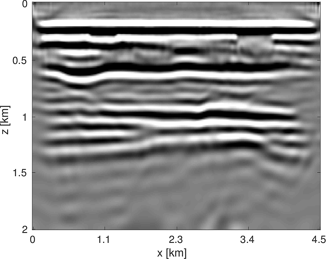
The seismic imaging problem aims to reconstruct a high resolution reflectivity map \(\delta m\) of the subsurface, given some smooth background model \(m_0\), by inverting the (overdetermined) Jacobian system \[ \begin{equation*} J(m_0) \delta m \approx \delta D. \end{equation*} \] In this simple example, \(\delta D\) is the image of the true perturbation under the Jacobian. Attempting to tackle the least-squares system directly \[ \begin{equation*} \min_{\delta m} \sum_{i_s \in S} \sum_{i_f \in F} \|J_{i_s,i_f} \delta m - \delta D_{i_s,i_f}\|_2^2, \end{equation*} \] where \(S\) indexes the sources and \(F\) indexes the frequencies, is computationally daunting due to the large number of sources and frequencies used. One straightforward approach is to randomly subsample sources and frequencies, i.e., choose \(S' \subset S\) and \(F' \subset F\) and solve \[ \begin{equation*} \min_{\delta m} \sum_{i_s \in S'} \sum_{i_f \in F'} \|J_{i_s,i_f} \delta m - \delta D_{i_s,i_f}\|_2^2, \end{equation*} \] but the Jacobian can become rank deficient in this case, despite it being full rank normally. One solution to this problem is to use sparse regularization coupled with randomized subsampling in order to force the iterates to head towards the true perturbation while still reducing the per-iteration costs. There have been a number of instances of incorporating sparsity of a seismic image in the Curvelet domain (Candes and Donoho, 2000; Candès and Donoho, 2004), in particular (Herrmann et al., 2008; Herrmann and Li, 2012; N. Tu and Herrmann, 2015). We use the Linearized Bregman method (Osher et al., 2011; J.-F. Cai et al., 2009b, 2009a), which solves \[ \begin{equation*} \begin{aligned} \min_{x} & \|x\|_1 + \lambda \|x\|_2^2 \\ \text{s.t. } & Ax = b. \end{aligned} \end{equation*} \] Coupled with random subsampling as in (F. Herrmann et al., 2015), the iterations are shown in Algorithm (2), a variant of which is used in (Chai et al., 2016). Here \(S_{\lambda}(x) = \text{sign}(x)\max(0,|x|-\lambda)\) is the componentwise soft-thresholding operator. In Listing (3), the reader will note the close adherence of our code to Algorithm (2), aside from some minor bookkeeping code and pre- and post-multiplying by the curvelet transform to ensure the sparsity of the signal. In this example, we place 300 equispaced sources and 400 receivers at the top of the model and generate data for 40 frequencies from 3-12 Hz. At each iteration of the algorithm, we randomly select 30 sources and 10 frequencies (corresponding to the 10 parallel workers we use) and set the number of iterations so that we perform 10 effective passes through the entire data. Compared to the image estimate obtained from an equivalent (in terms of number of PDEs solved) method solving the least-squares problem with the LSMR (Fong and Saunders, 2011) method, the randomly subsampled method has made significantly more progress towards the true solution, as shown in Figure (9).
for \(k = 1, 2, \dots, T\)
Draw a random subset of indices \(I_k\)
\(z_{k+1} \gets z_k - t_k A_{I_k}^T (b_{I_k} - A_{I_k}x_k)\)
\(x_{k+1} \gets S_{\lambda}(x_k)\)
for k=1:T
  % Draw a random subset of sources and frequencies
  Is = rand_subset(nsrc,round(0.2*nsrc));
  If = rand_subset(nfreq,parpool_size());
  % Mask the objective to the sources/frequencies drawn
  srcfreqmask = false(nsrc,nfreq);
  srcfreqmask(Is,If) = true;
  params.srcfreqmask = srcfreqmask;
  % Construct the subsampled Jacobian operator + data
  A = oppDF(m0,Q,model,params);
  b = distributed_subsample_data(b_full,Is,If);
  % Linearized Bregman algorithm
  r = A*x-b;
  ATr = A'*r;
  t = norm(r)^2/norm(ATr)^2;
  z = z - t*ATr;
  x = C'*softThreshold(C*z,lambda);
end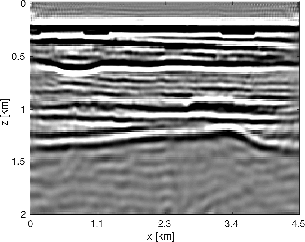
Electromagnetic Conductivity Inversion
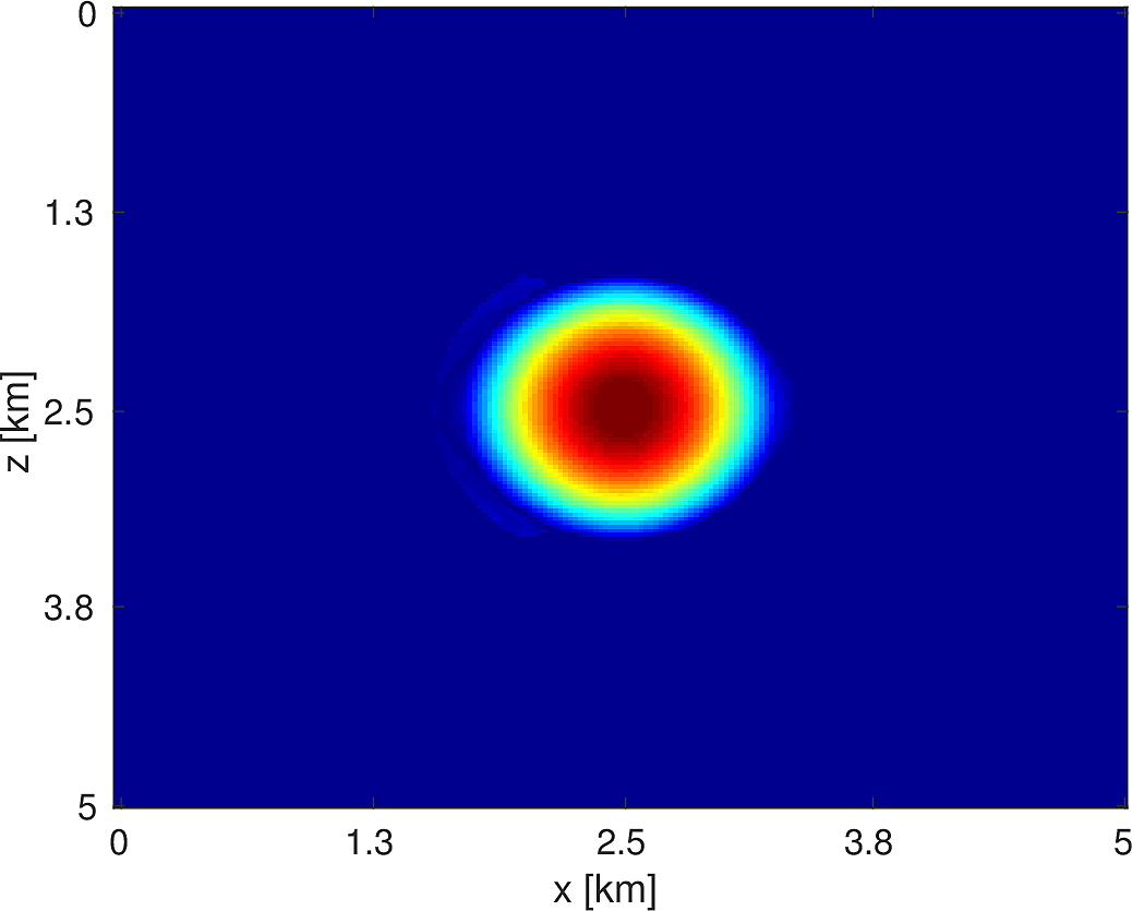
To demonstrate the modular and flexible nature of our software framework, we replace the finite difference Helmholtz PDE with a simple finite volume discretization of the variable coefficient Poisson equation \[ \begin{equation*} \nabla(\sigma \cdot \nabla u) = q \end{equation*} \] where \(\sigma\) is the spatially-varying conductivity coefficient. We discretize the field on the vertices of a regular rectangular mesh and \(\sigma\) at the cell centers, which results in the system matrix, denoted \(H(\sigma)\), written abstractly as \[ \begin{equation*} H(\sigma) = \sum_{i=1}^{5} A_i \text{diag}(B_i \sigma) \end{equation*} \] for constant matrices \(A_i, B_i\). This form allows us to easily derive expressions for \(T : \delta \sigma \mapsto DH(\sigma)[\delta m]u\) and \(T^*\) as \[ \begin{equation*} \begin{aligned} T\delta \sigma &= \sum_{i=1}^{5} A_i \text{diag}(B_i \delta \sigma)u \\ T^* z &= \sum_{i=1}^{5} B_i^H \text{diag}(\overline{u}) A_i^H z. \end{aligned} \end{equation*} \] With these expressions in hand, we merely can slot the finite volume discretization and the corresponding directional derivative functions in to our framework without modifying any other code.
Consider a simple constant conductivity model containing a square anomaly with a 20% difference compared to the background, encompassing a region that is 5km x 5km with a grid spacing of 10m, as depicted in Figure (10). We place 100 equally spaced sources and receivers at depths \(z = 400m\) and \(z = 1600m\), respectively. The pointwise constraints we use are the true model for \(z < 400m\) and \(z > 1600m\) and, for the region in between, we set \(\sigma_{\text{min}} = \min_{x} \sigma(x)\) and \(\sigma_{\text{max}} = 2\max_{x} \sigma(x)\). Our initial model is a constant model with the correct background conductivity, shown in Figure (10). Given a current estimate of the conductivity \(\sigma_k\), we minimize a quadratic model of the objective subject to bound constraints, i.e., \[ \begin{equation*} \begin{aligned} \sigma_{k+1} = \argmin_{\sigma} & \langle \sigma-\sigma_k, g_k \rangle + \dfrac{1}{2} \langle \sigma-\sigma_k, H_k(\sigma-\sigma_k) \rangle \\ \text{s.t. } &\; \sigma_{\text{min}} \le \sigma \le \sigma_{\text{max}} \end{aligned} \end{equation*} \] where \(g_k,H_k\) are the gradient and Gauss-Newton Hessian, respectively. We solve \(5\) of these subproblems, using \(5\) objective/gradient evaluations to solve each subproblem using the bound constrained LBFGS method of (M. W. Schmidt et al., 2009). As we do not impose any constraints on the model itself and the PDE itself is smoothing, we are able to recover a very smooth version of the true model, shown in Figure (10), with the attendant code shown in Listing (4). This discretization and optimization setup is by no means the optimal method to invert such conductivity models but we merely outline how straightforward it is to incorporate different PDEs in to our framework. Techniques such as total variation regularization (Abubaker and Van Den Berg, 2001) can be incorporated in to this framework by merely modifying our objective function.
obj = misfit_setup(sigma0,Q,D,model,params);
sigma = sigma0;
for i=1:5
  % Evaluate objective
  [f,g,h] = obj(sigma);
  % Construct quadratic model
  q = @(x) quadratic_model(g,h,x,sigma);
  % Minimize quadratic model, subject to pointwise constraints
  sigma = minConf_TMP(q,sigma,sigma_min,sigma_max,opts);
end

Stochastic Full Waveform Inversion
Our software design makes it relatively straightforward to apply the same inversion algorithm to both a 2D and 3D problem in turn, while changing very little in the code itself. We consider the following algorithm for inversion, which will allow us to handle the large number of sources and number of model parameters, as well as the necessity of pointwise bound constraints (Herrmann and Peters, 2016) on the intermediate models. Our problem has the form \[ \begin{equation*} \begin{aligned} \min_{m} & \dfrac{1}{N_s} \sum_{i=1}^{N_s} f_i(m) \\ \text{s.t. } & \; m \in C \end{aligned} \end{equation*} \] where \(m\) is our model parameter (velocity or slowness), \(f_i(m) = \frac{1}{2}\|P_r H(m)^{-1}q_i - d_i\|_2^2\) is the least-squares misfit for source \(i\), and \(C\) is our convex constraint set, which is \(C = \{ m : m_{LB} \le m \le m_{UB} \}\) in this case. When we have \(p\) parallel processes and \(N_s \gg p\) sources, in order to efficiently make progress toward the solution of the above problem, we stochastically subsample the objective and approximately minimize the resulting problem, i.e., at the \(k\)th iteration we solve \[ \begin{equation*} \begin{aligned} m_{k} = \argmin_{m} & \dfrac{1}{|I_k|} \sum_{i \in I_k} f_i(m) \\ \text{s.t. } &\; m \in C \end{aligned} \end{equation*} \] for \(I_k \subset \{1, \dots, N_s\}\) drawn uniformly at random and \(|I_k| = p \ll N_s\). We use the approximate solution \(m_k\) as a warm start for the next problem and repeat this process a total of \(T\) times. Given that our basic unit of work in these problems is computing the solution of a PDE, we limit the number of iterations for each subproblem solution so that each subproblem can be evaluated at a constant multiple of evaluating the objective and gradient with the full data, i.e., \(r_{\text{sub}} \lceil \frac{N_s}{p} \rceil\) iterations for a constant \(r_{\text{sub}}\). If an iteration stagnates, i.e., if the line search fails, we increase the size of \(|I_k|\) by a fixed amount. This algorithm is similar in spirit to the one proposed in (Leeuwen and Herrmann, 2014).
2D Model — BG Compass
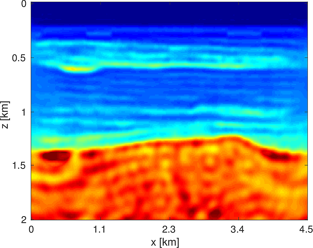
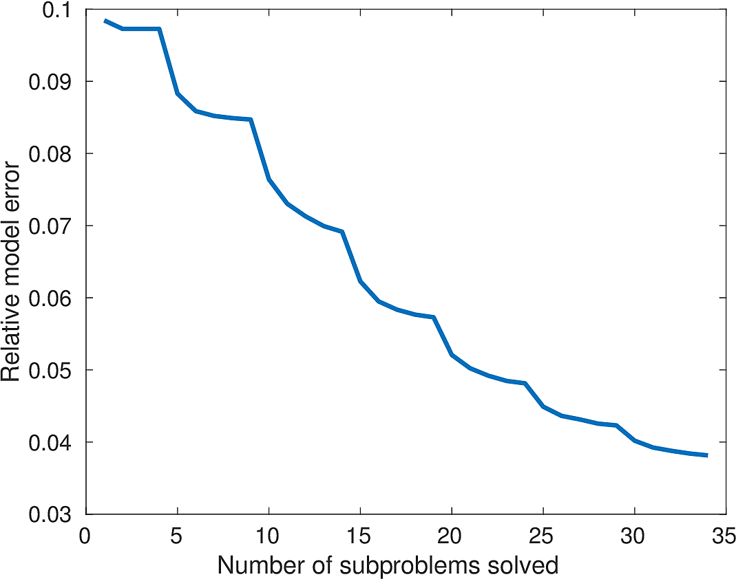
We apply the above algorithm to the BG Compass model, with the same geometry and source/receiver configuration as outlined in Section (#fwiexample). We limit the total number of passes over the entire data to be equal to \(50\%\) of those used in the previous example, with \(10\) re-randomization steps and \(r_{\text{sub}} = 2\). Our results are shown in Figure (11). Despite the smaller number of overall PDEs solved, the algorithm converges to a solution that is qualitatively hard to distinguish from Figure (8). The overall model error as a function of number of subproblems solved is depicted Figure (12). The model error stagnates as the number of iterations in a given frequency batch rises and continues to decrease when a new frequency batch is drawn.


3D Model - Overthrust
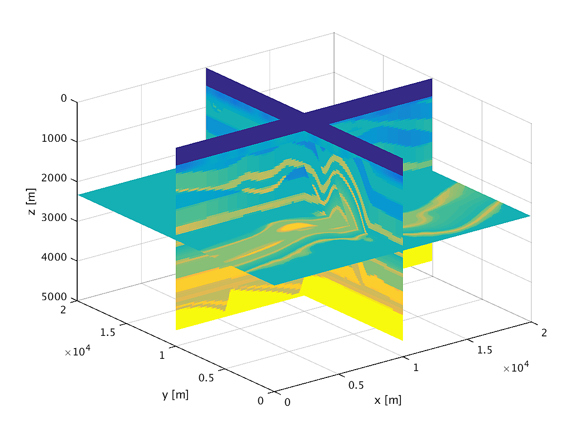
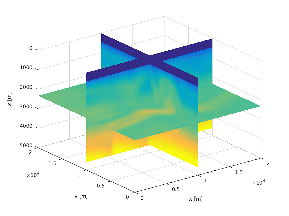
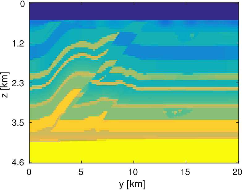
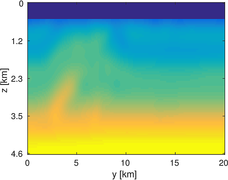
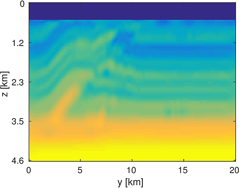
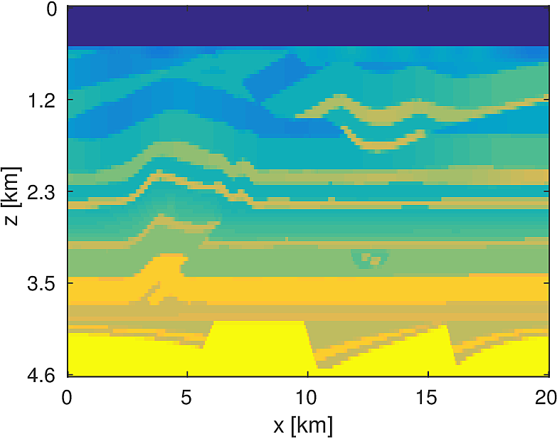
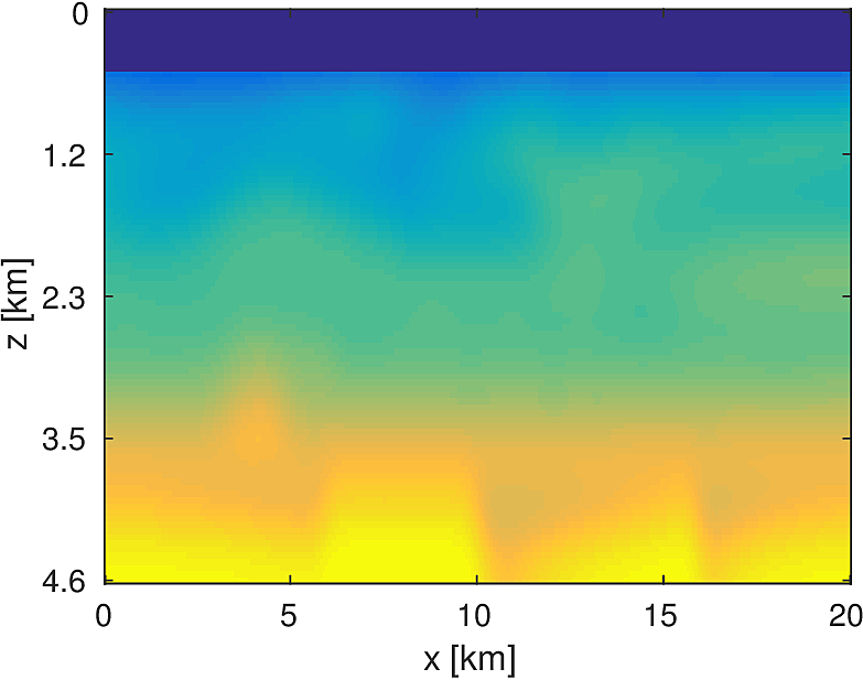
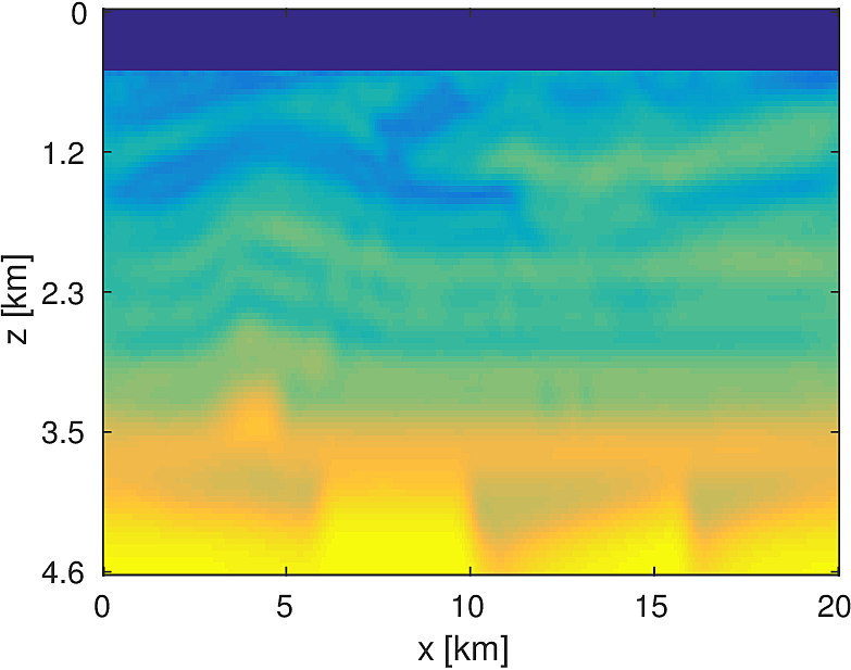
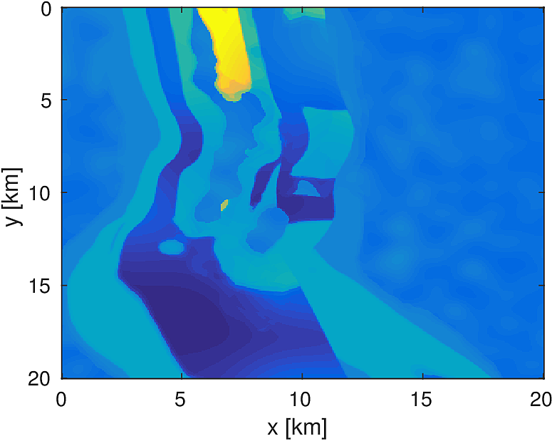
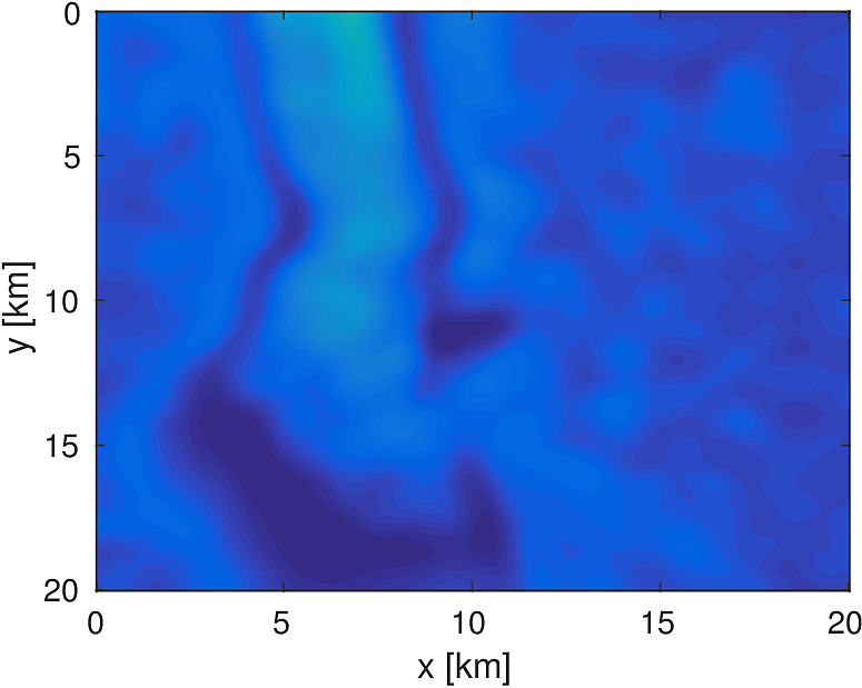
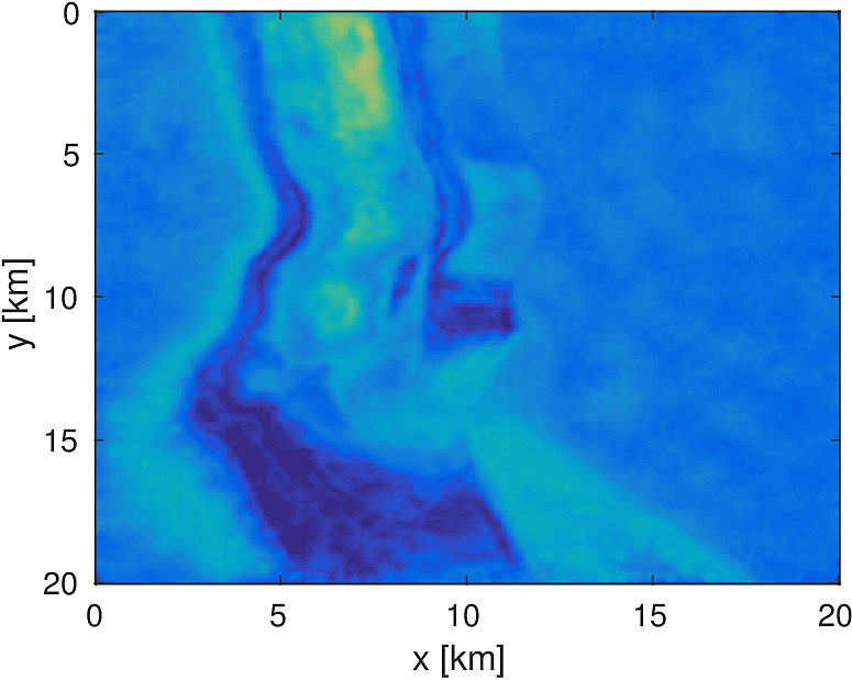
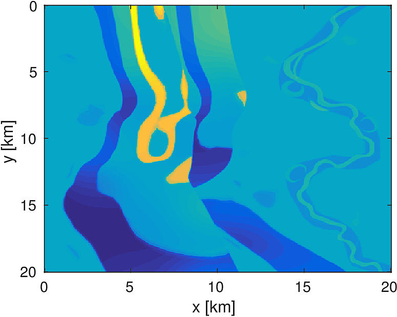
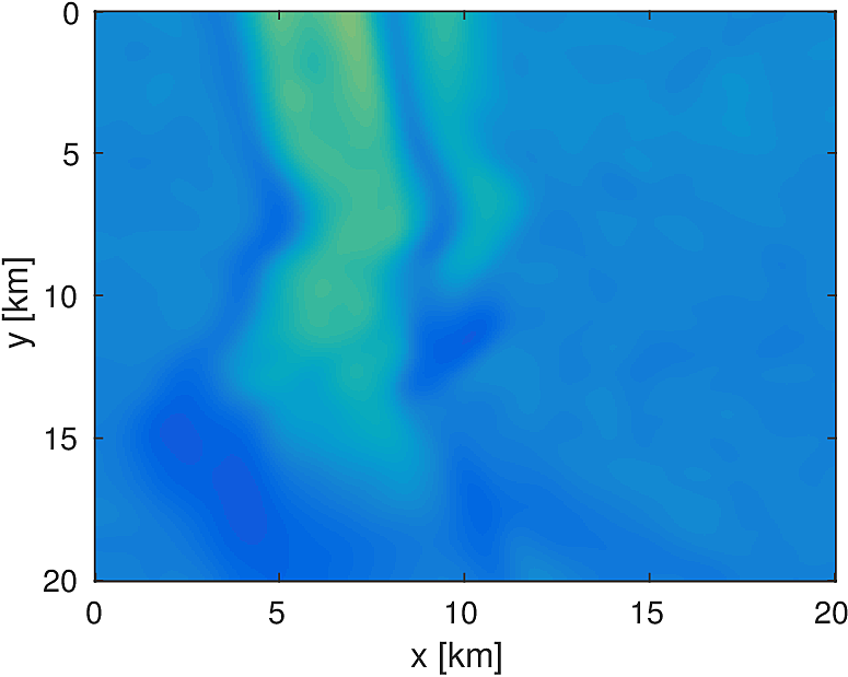
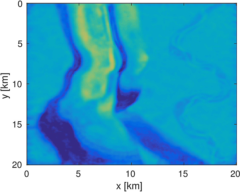
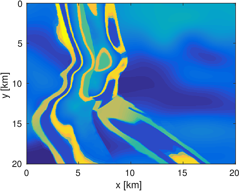
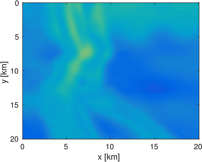
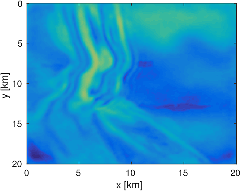
We apply the aforementioned algorithm to the SEG/EAGE Overthrust model, which spans 20km x 20km x 5km and is discretized on a 50m x 50m x 50m grid with a 500m deep water layer and minimum and maximum velocities of . The ocean floor is covered with a 50 x 50 grid of sources, each with 400m spacing, and a 396 x 396 grid of receivers, each with 50m spacing. The frequencies we use are in the range of \(3-5.5Hz\) with \(0.25 Hz\) sampling, corresponding to 4s of data in the time domain, and inverted a single frequency at a time. The number of wavelengths in the \(x,y,z\) directions vary from \((40,40,9)\) to \((74,74,17)\), respectively, with the number of points per wavelength varying from 9.8 at the lowest frequency to 5.3 at the highest frequency. The model is clamped to be equal to the true model in the water layer and is otherwise allowed to vary between the maximum and minimum velocity values. In practical problems, some care must be taken to ensure that discretization discrepancies between the boundary of the water and the true earth model are minimized. Our initial model is a significantly smoothed version of the true model and we limit the number of stochastic redraws to \(T=3\), so that we are performing the same amount of work as evaluating the objective and gradient three times with the full data. The number of unknown parameters is 14,880,000 and the fields are inverted on a grid with 39,859,200 points, owing to the PML layers in each direction. We use 100 nodes with 4 Matlab workers each of the Yemoja cluster for this computation. Each node has 128GB of RAM and a 20-core Intel processor. We use 5 threads for each matrix-vector product and subsample sources so that each Matlab worker solves a single PDE at a time (i.e., \(|I_k| = 400\) in the above formulation) and set the effective number of passes through the data for each subproblem to be one, i.e., \(r_{\text{sub}}=1\). Despite the limited number of passes through the data, our code is able to make substantial progress towards the true model, as shown in Figures (14) and (15). Unlike in the 2D case, we are limited in our ability to invert higher frequencies in a reasonable amount of time and therefore our inverted results do not fully resolve the fine features, especially in the deeper parts of the model.
Discussion
There are a number of problem-specific constraints that have motivated our design decisions thus far. Computing solutions to the Helmholtz equation in particular is challenging due to the indefiniteness of the underlying system for even moderate frequencies and the sampling requirements of a given finite difference stencil. These challenges preclude one from simply employing the same sparse-matrix techniques in 2D for the 3D case. Direct methods that store even partial LU decomposition of the system matrix are infeasible from a memory perspective, unless one allows for using multiple nodes to compute the PDE solutions. Even in that case, one can run in to resiliency issues in computational environments where nodes have a non-zero probability of failure over the lifetime of the computation. Regardless of the dimensionality, our unified interface for multiplying and dividing the Helmholtz system with a vector abstracts away the implementation specific details of the underlying matrix, while still allowing for high performance. These design choices give us the ability to scale from simple 2D problems on 4 cores to realistically sized 3D problems running on 2000 cores with minimal engineering effort.
Although our choice of Matlab has enabled us to succinctly design and prototype our code, there have been a few stumbling blocks as a result of this language choice. There is an onerous licensing issue for the Parallel Toolbox, which makes scaling to a large number of workers costly. The Parallel Toolbox is built on MPI, which is simply insufficient for performing large scale computations in an environment that can be subject to disconnections and node failures and cannot be swapped out for another parallelization scheme within Matlab itself. In an environment where one does not have full control over the computational hardware, such as on Amazon’s cloud computing services, this paradigm is untenable. For interfacing with the C/Fortran language, there is a large learning curve for compiling MEX files, which are particularly constructed C files that can be called from with Matlab. Matlab offers its Matlab Coder product that allows one to, in principle, compile any function in to a MEX file, and thus reap potential performance benefits. The compilation process has its limits in terms of functionality, however, and cannot, for instance, compile our framework easily.
Thankfully, there have been a few efforts to help alleviate these issues. The relatively new numerical computing language Julia has substantially matured in the last few years, making it a viable competitor to Matlab. Julia aims to bridge the gap between an interpreted and a compiled language, the former being easier to prototype in and the latter being much faster by offering a just-in-time compiler, which balances ease of use and performance. Julia is open source, whereas Matlab is decidedly not, allows for a much more fine-grained control over parallelization, and has other attractive features such as built-in interfacing to C, is strongly-typed, although flexibly so, and has a large, active package ecosystem. We aim to reimplement the framework described in this paper in Julia in the future. The Devito framework (Lange et al., 2016) is another such approach to balance the high-level mathematics and low-level performance in PDE-constrained problems specifically through the compilation of symbolic Python to C on-the-fly. Devito incurs some initial setup time to process the symbolic expressions of the PDEs and compile them in to runnable C binaries, but this overhead is negligible compared to the cost of time-stepping solutions and only has to be performed once for a PDE with fixed parameters. This is one possible option to speed up matrix-vector products, or allow for user-specified order of accuracy at runtime, if the relevant complex-valued extensions can be written. We leave this as an option for future work.
Conclusion
The designs outlined in this paper make for an inversion framework that successfully obfuscates the inner workings of the construction, solution, and recombination of solutions of PDE systems. As a result, the high-level interfaces exposed to the user allow a researcher to easily construct algorithms dealing with the outer structure of the problem, such as stochastic subsampling or solving Newton-type methods, rather than being hindered by the complexities of, for example, solving linear systems or distributing computation. This hierarchical and modular approach allows us to delineate the various components associated to these computations in a straightforward and demonstrably correct way, without sacrificing performance. Moreover, we have demonstrated that this design allows us to easily swap different PDE stencils, or even PDEs themselves, while still keeping the outer, high-level interfaces intact. This design allows us to apply a large number high-level algorithms to large-scale problems with minimal amounts of effort.
With this design, we believe that we have struck the right balance between readability and performance and, by exposing the right amount of information at each level of the software hierarchy, researchers should be able to use this codebase as a starting point for developing future inversion algorithms.
Acknowledgements
The authors would like to thank Tristan van Leeuwan for his helpful suggestions. This research was carried out as part of the SINBAD project with the support of the member organizations of the SINBAD Consortium. Curt Da Silva has been supported by the CGS D award from the National Sciences and Engineering Research Council of Canada (NSERC) throughout the duration of this work. The authors wish to acknowledge the SENAI CIMATEC Supercomputing Center for Industrial Innovation, with support from Shell and the Brazilian Authority for Oil, Gas and Biofuels (ANP), for the provision and operation of computational facilities and the commitment to invest in Research & Development.
Appendix
A ‘User Friendly’ Guide to Basic Inverse Problems
For our framework, not only do we want to solve \(\eqref{mainprob}\) directly, but allow researchers to explore other subproblems associated to the primary problem, such as the linearized problem (Herrmann and Li, 2011) and the full-Newton trust region subproblem. As such, we are not only interested in the objective function and gradient, but also other intermediate quantities based on differentiating the state equation \(H(m)u(m) = q\). A standard approach to deriving these quantities is the adjoint-state approach, described for instance in (Plessix, 2006), but the results we outline below are slightly more elementary and do not make use of Lagrange multipliers.
Rather than focusing on differentiating the expressions in \(\eqref{mainprob}\) directly, we find it useful to consider directional derivatives various quantities and their relationships to the gradient. That is to say, for a sufficiently smooth function \(f(m)\) that can be scalar, vector, or matrix-valued, the directional dervative in the direction \(\delta m\), denoted \(Df(m)[\delta m]\), is a linear function of \(\delta m\) that satisfies \[ \begin{equation*} Df(m)[\delta m] = \lim_{t \to 0} \dfrac{f(m+t\delta m)-f(m)}{t}. \end{equation*} \] The most important part of the directional derivative, for the purposes of the following calculations, is that \(Df(m)[\delta m]\) is the same mathematical object as \(f(m)\), i.e., if \(f(m)\) is a matrix, so is \(Df(m)[\delta m]\).
For a given inner product \(\langle \cdot, \cdot \rangle\), the gradient of \(f(m)\), denoted \(\nabla f(m)\), is the unique vector that satisfies \[ \begin{equation*} \langle \nabla f(m), \delta m\rangle = Df(m)[\delta m] \quad \forall \delta m \end{equation*} \] If we are not terribly worried about specifying the exact vectors spaces in which these objects live and treat them as we’d expect them to behave (i.e., satisfying product, chain rules, commuting with matrix transposes, complex conjugation, linear operators, etc.), the resulting derivations become much more manageable.
Starting from the baseline expression for the misfit \(f(m)\) and differentiating, using the chain rule, we have that \[ \begin{equation*} \begin{aligned} f(m) &= \phi(P_r H(m)^{-1}q, d) = \phi(P_r u(m),d)\\ Df(m)[\delta m] &= D\phi(r(m),d)[Dr(m)[\delta m]]\\ r(m) &= P_r u(m)\\ Dr(m)[\delta m] &= P_r Du(m)[\delta m] \end{aligned} \end{equation*} \] In order to determine the expression for \(Du(m)[\delta m]\), we differentiate the state equation, \[ \begin{equation*} H(m)u(m) = q, \end{equation*} \] in the direction \(\delta m\) using the product rule to obtain \[ \begin{equation} \begin{split} DH(m)[\delta m]u(m) + H(m)Du(m)[\delta m] = 0\\ Du(m)[\delta m] = H(m)^{-1} (-DH(m)[\delta m]u(m)). \end{split} \label{dU2} \end{equation} \] For the forward modelling operator \(F(m)\), \(DF(m)[\delta m]\) is the Jacobian or so-called linearized born-modelling operator in geophysical parlance. Since, for any linear operator \(A\), its transpose satisfies \[ \begin{equation*} \langle Ax, y\rangle = \langle x, A^T y\rangle \end{equation*} \] for any appropriately sized vectors \(x, y\), in order to determine the transpose of \(Dr(m)[\delta m]\), we merely take the inner product with an arbitrary vector \(y\), “isolate” the vector \(\delta m\) on one side of the inner product. The other side is the expression for the adjoint operator. In this case, we have that \[ \begin{equation*} \begin{aligned} \langle DF(m)[\delta m], y \rangle &= \langle P_r H(m)^{-1}(-DH(m)[\delta m]u(m)), y \rangle\\ &= \langle H(m)^{-1}(-DH(m)[\delta m]u(m)),P_r^T y\rangle\\ &= \langle DH(m)[\delta m]u(m), -H(m)^{-H} P_r^T y \rangle\\ &= \langle T\delta m, -H(m)^{-H} P_r^T y \rangle\\ &= \langle \delta m, T^* (-H(m)^{-H} P_r^T y) \rangle \end{aligned} \end{equation*} \] In order to completely specify the adjoint of \(DF(m)[\delta m]\), we need to specify the adjoint of \(T\delta m = DH(m)[\delta m]u(m)\) acting on a vector. This expression is particular to the form of the PDE with which we’re working. For instance, discretizing the constant-density acoustic Helmholtz equation with finite differences results in \[ \begin{equation*} \nabla^2u(x) + \omega^2 m(x)u(x) = q(x) \end{equation*} \] with particular matrices \(L, A\) discretizing the Laplacian and identity operators, respectively, yields the linear system \[ \begin{equation*} Lu + \omega^2 A\text{diag}(m)u = q. \end{equation*} \] Therefore, we have the expression \[ \begin{equation} \begin{aligned} T \delta m &:= DH(m)[\delta m]u(m)\\ &= \omega^2 A\text{diag}(\delta m)u(m)\\ &= \omega^2 A\text{diag}(u(m))\delta m, \end{aligned} \label{dH} \end{equation} \] whose adjoint is clearly \[ \begin{equation} T^* = \omega^2\text{diag}(\overline{u(m)})A^H \label{dHadj} \end{equation} \] with directional derivative \[ \begin{equation} DT^*[\delta m, \delta u] = \omega^2\text{diag}(\overline{\delta u})A^H. \label{DTadj} \end{equation} \] Our final expression for \(DF(m)[\cdot]^*y\) is therefore \[ \begin{equation*} DF(m)[\cdot]^*y = \omega^2 \text{diag}(\overline{u(m)})A^H (-H(m)^{-H} P_r^T y) \end{equation*} \] Setting \(y = \nabla \phi(P_r u(m))\), \(v(m) = -H(m)^{-H} P_r^T y\) yields the familiar expression for the gradient of \(f(m)\) \[ \begin{equation*} \nabla f(m) = \omega^2 \text{diag}(\overline{u(m)})A^H H(m)^{-H}P_r^T (-\nabla \phi(u(m))) \end{equation*} \] This sort of methodology can be used to symbolically differentiate more complicated expressions as well as compute higher order derivatives of \(f(m)\). Let us write \(\nabla f(m)\) more abstractly as \[ \begin{equation*} \nabla f(m) = T(m,u)^* v(m), \end{equation*} \] which will allow us to compute the Hessian as \[ \begin{equation*} \nabla^2 f(m)\delta m = DT(m,u)^*[\delta m,Du[\delta m]] v(m) + T(m,u)^* Dv(m)[\delta m]. \end{equation*} \] Here, \(Du[\delta m]\) is given in \(\eqref{dU2}\) and \(DT(m,u)^*[\delta m, \delta u]\) is given in \(\eqref{DTadj}\), for the Helmholtz equation. We compute \(Dv(m)[\delta m]\) by differentiating \(v(m)\) as \[ \begin{equation*} \begin{aligned} Dv(m)[\delta m] &= H(m)^{-H} DH(m)[\delta m]^H v(m) -H(m)^{-H} P_r^T (\nabla^2 \phi[P_r Du(m)[\delta m]])\\ &= H(m)^{-H}( DH(m)[\delta m]^H v(m) - P_r^T (\nabla^2 \phi[P_r Du(m)[\delta m]]) ) \end{aligned} \end{equation*} \] which completes our derivation for the Hessian-vector product.
Derivative expressions for Waveform Reconstruction Inversion
From \(\eqref{wrifieldeq}\), we have that the augmented wavefield \(u(m)\) solves the least-squares system \[ \begin{equation*} \begin{split} \min_{u} \left \| \left[ {\begin{array}{c} P_r \\ \lambda H(m) \end{array} } \right] u - \left[ { \begin{array}{c} d \\ \lambda q \end{array} } \right] \right\|_2^2, \end{split} \end{equation*} \] i.e., \(u(m)\) solves the normal equations \[ \begin{equation*} (P_r^T P_r + \lambda^2 H(m)^H H(m))u(m) = P_r^T d + \lambda^2 H(m)^H q. \end{equation*} \] For the objective \(\phi(m,u) = \dfrac{1}{2} \|P_r u - d\|_2^2 + \dfrac{\lambda^2}{2} \|H(m)u - q\|_2^2\), the corresponding WRI objective is \(f(m) = \phi(m,u(m))\). Owing to the variable projection structure of this objective, the expression for \(\nabla_m f(m)\), by (A. Y. Aravkin and Van Leeuwen, 2012), is \[ \begin{equation*} \begin{aligned} \nabla_m f(m) &= \nabla_m \phi(m,u(m)) \\ &= \lambda^2 T(m,u(m))^* (H(m)u(m) - q), \end{aligned} \end{equation*} \] which is identical to the original adjoint-state formulation, except evaluated at the wavefield \(u(m)\).
The Hessian-vector product is therefore \[ \begin{equation*} \nabla^2_m f(m) = DT(m,u(m))[\delta m, Du(m)[\delta m]]^* (H(m)u(m)-q) + T(m,u(m))^* (DH(m)[\delta m]u(m) + H(m)Du(m)[\delta m]). \end{equation*} \] As previously, the expressions for \(DH(m)[\delta m]\) and \(DT(m,u)[\delta m, \delta u]^*\) are implementation specific. It remains to derive an explicit expression for \(Du(m)[\delta m]\) below.
Let \(G(m) = (P_r^T P_r + \lambda^2 H(m)^H H(m))\), \(r(m) = P_r^T d + \lambda^2 H(m)^H q\), so the above equation reads as \(G(m)u(m) = r(m)\).
We differentiate this equation in the direction \(\delta m\) to obtain \[ \begin{equation*} \begin{split} DG(m)[\delta m] u(m) + G(m)Du(m)[\delta m] = Dr(m)[\delta m] \\ \rightarrow Du(m)[\delta m] = G(m)^{-1} (Dr(m)[\delta m] - DG(m)[\delta m]u(m)). \end{split} \end{equation*} \] Since \(DG(m)[\delta m] = \lambda^2 (DH(m)[\delta m]^{H} H(m) + H(m)^HDH(m)[\delta m])\) and \(Dr(m)[\delta m] = \lambda^2 DH(m)[\delta m]^H q\), we have that \[ \begin{equation*} Du(m)[\delta m] = \lambda^2 G(m)^{-1}( - H(m)^H DH(m)[\delta m]u(m) + DH(m)[\delta m]^H( H(m)u(m)- q) ). \end{equation*} \]
Abubaker, A., and Van Den Berg, P. M., 2001, Total variation as a multiplicative constraint for solving inverse problems: IEEE Transactions on Image Processing, 10, 1384–1392.
Adler, A., Gaburro, R., and Lionheart, W., 2011, Electrical impedance tomography: In Handbook of mathematical methods in imaging (pp. 599–654). Springer.
Aravkin, A. Y., and Van Leeuwen, T., 2012, Estimating nuisance parameters in inverse problems: Inverse Problems, 28, 115016.
Aravkin, A., Friedlander, M. P., Herrmann, F. J., and Van Leeuwen, T., 2012, Robust inversion, dimensionality reduction, and randomized sampling: Mathematical Programming, 1–25.
Aravkin, A., Van Leeuwen, T., and Herrmann, F., 2011, Robust full-waveform inversion using the student’s t-distribution: In SEG technical program expanded abstracts 2011 (pp. 2669–2673). Society of Exploration Geophysicists.
Balay, S., Brown, J., Buschelman, K., Eijkhout, V., Gropp, W., Kaushik, D., … Zhang, H., 2012, PETSc users manual revision 3.3: Computer Science Division, Argonne National Laboratory, Argonne, IL.
Berenger, J.-P., 1994, A perfectly matched layer for the absorption of electromagnetic waves: Journal of Computational Physics, 114, 185–200.
Bezanson, J., Edelman, A., Karpinski, S., and Shah, V. B., 2014, Julia: A fresh approach to numerical computing: ArXiv Preprint ArXiv:1411.1607.
Biros, G., and Ghattas, O., 2005, Parallel lagrange–Newton–Krylov–Schur methods for pDE-constrained optimization. part i: The krylov–Schur solver: SIAM Journal on Scientific Computing, 27, 687–713.
Borcea, L., 2002, Electrical impedance tomography: Inverse Problems, 18, R99.
Bottou, L., 1998, Online learning and stochastic approximations: On-Line Learning in Neural Networks, 17, 142.
Bottou, L., 2010, Large-scale machine learning with stochastic gradient descent: In Proceedings of cOMPSTAT’2010 (pp. 177–186). Springer.
Boubendir, Y., Antoine, X., and Geuzaine, C., 2012, A quasi-optimal non-overlapping domain decomposition algorithm for the helmholtz equation: Journal of Computational Physics, 231, 262–280.
Briggs, W. L., Henson, V. E., and McCormick, S. F., 2000, A multigrid tutorial: SIAM.
Cai, J.-F., Osher, S., and Shen, Z., 2009a, Convergence of the linearized bregman iteration for l1-norm minimization: Mathematics of Computation, 78, 2127–2136.
Cai, J.-F., Osher, S., and Shen, Z., 2009b, Linearized bregman iterations for compressed sensing: Mathematics of Computation, 78, 1515–1536.
Calandra, H., Gratton, S., Pinel, X., and Vasseur, X., 2013, An improved two-grid preconditioner for the solution of three-dimensional helmholtz problems in heterogeneous media: Numerical Linear Algebra with Applications, 20, 663–688. doi:10.1002/nla.1860
Candes, E. J., and Donoho, D. L., 2000, Curvelets: A surprisingly effective nonadaptive representation for objects with edges:. DTIC Document.
Candès, E. J., and Donoho, D. L., 2004, New tight frames of curvelets and optimal representations of objects with piecewise c2 singularities: Communications on Pure and Applied Mathematics, 57, 219–266.
Chai, X., Yang, M., Witte, P., Wang, R., Fang, Z., and Herrmann, F., 2016, A linearized bregman method for compressive waveform inversion: In SEG technical program expanded abstracts 2016 (pp. 1449–1454). Society of Exploration Geophysicists.
Chen, J.-B., 2014, A 27-point scheme for a 3D frequency-domain scalar wave equation based on an average-derivative method: Geophysical Prospecting, 62, 258–277.
Chen, Z., Cheng, D., Feng, W., and Wu, T., 2013, AN oPTIMAL 9-pOINT fINITE dIFFERENCE sCHEME fOR tHE hELMHOLTZ eQUATION wITH pML.: International Journal of Numerical Analysis & Modeling, 10.
Cheney, M., Isaacson, D., and Newell, J. C., 1999, Electrical impedance tomography: SIAM Review, 41, 85–101.
Chew, W., Jin, J., and Michielssen, E., 1997, Complex coordinate stretching as a generalized absorbing boundary condition: Microwave and Optical Technology Letters, 15, 363–369.
Cimpeanu, R., Martinsson, A., and Heil, M., 2015, A parameter-free perfectly matched layer formulation for the finite-element-based solution of the helmholtz equation: Journal of Computational Physics, 296, 329–347.
Cockett, R., Kang, S., Heagy, L. J., Pidlisecky, A., and Oldenburg, D. W., 2015, SimPEG: An open source framework for simulation and gradient based parameter estimation in geophysical applications: Computers & Geosciences, 85, 142–154.
Cohen, G., 2013, Higher-order numerical methods for transient wave equations: Springer Science & Business Media.
De Zeeuw, P. M., 1990, Matrix-dependent prolongations and restrictions in a blackbox multigrid solver: Journal of Computational and Applied Mathematics, 33, 1–27.
E. van den Berg, M. P. F., 2014, Spot - a linear-operator toolbox:. “http://www.cs.ubc.ca/labs/scl/spot/”.
Engquist, B., and Ying, L., 2011, Sweeping preconditioner for the helmholtz equation: Moving perfectly matched layers: Multiscale Modeling & Simulation, 9, 686–710.
Erlangga, Y. A., Vuik, C., and Oosterlee, C. W., 2004, On a class of preconditioners for solving the helmholtz equation: Applied Numerical Mathematics, 50, 409–425.
Farrell, P. E., Ham, D. A., Funke, S. W., and Rognes, M. E., 2013, Automated derivation of the adjoint of high-level transient finite element programs: SIAM Journal on Scientific Computing, 35, C369–C393.
Fong, D. C.-L., and Saunders, M., 2011, LSMR: An iterative algorithm for sparse least-squares problems: SIAM Journal on Scientific Computing, 33, 2950–2971.
Friedlander, M. P., and Schmidt, M., 2012, Hybrid deterministic-stochastic methods for data fitting: SIAM Journal on Scientific Computing, 34, A1380–A1405.
Gander, M. J., and Zhang, H., 2013, Domain decomposition methods for the helmholtz equation: A numerical investigation: In Domain decomposition methods in science and engineering xX (pp. 215–222). Springer.
Gordon, D., and Gordon, R., 2010, CARP-cG: A robust and efficient parallel solver for linear systems, applied to strongly convection dominated {pDEs}: Parallel Computing, 36, 495–515. doi:http://dx.doi.org/10.1016/j.parco.2010.05.004
Gray, S. H., Etgen, J., Dellinger, J., and Whitmore, D., 2001, Seismic migration problems and solutions: Geophysics, 66, 1622–1640.
Grippo, L., Lampariello, F., and Lucidi, S., 1989, A truncated newton method with nonmonotone line search for unconstrained optimization: Journal of Optimization Theory and Applications, 60, 401–419.
Hastings, F. D., Schneider, J. B., and Broschat, S. L., 1996, Application of the perfectly matched layer (pML) absorbing boundary condition to elastic wave propagation: The Journal of the Acoustical Society of America, 100, 3061–3069.
Heroux, M. A., Bartlett, R. A., Howle, V. E., Hoekstra, R. J., Hu, J. J., Kolda, T. G., … others, 2005, An overview of the trilinos project: ACM Transactions on Mathematical Software (TOMS), 31, 397–423.
Herrmann, F. J., and Li, X., 2011, Efficient least-squares migration with sparsity promotion: EAGE annual conference proceedings. EAGE; EAGE. Retrieved from https://www.slim.eos.ubc.ca/Publications/Public/Conferences/EAGE/2011/herrmann11EAGEefmsp/herrmann11EAGEefmsp.pdf
Herrmann, F. J., and Li, X., 2012, Efficient least-squares imaging with sparsity promotion and compressive sensing: Geophysical Prospecting, 60, 696–712.
Herrmann, F. J., and Peters, B., 2016, Constraints versus penalties for edge-preserving full-waveform inversion: SEG workshop on where are we heading with fWI; dallas.
Herrmann, F. J., Moghaddam, P., and Stolk, C. C., 2008, Sparsity-and continuity-promoting seismic image recovery with curvelet frames: Applied and Computational Harmonic Analysis, 24, 150–173.
Herrmann, F., Tu, N., and Esser, E., 2015, Fast “online” migration with compressive sensing: 77th annual international conference and exhibition, eAGE: Extended Abstracts, Http://dx. Doi. Org/10.3997/2214-4609.201412942.
Hicks, G. J., 2002, Arbitrary source and receiver positioning in finite-difference schemes using kaiser windowed sinc functions: Geophysics, 67, 156–165.
Holberg, O., 1987, Computational aspects of the choice of operator and sampling interval for numerical differentiation in large-scale simulation of wave phenomena: Geophysical Prospecting, 35, 629–655.
Jo, C.-H., Shin, C., and Suh, J. H., 1996, An optimal 9-point, finite-difference, frequency-space, 2-d scalar wave extrapolator: Geophysics, 61, 529–537.
Kanamori, H., 1978, Quantification of earthquakes: Nature, 271, 411–414.
Knepley, M. G., Katz, R. F., and Smith, B., 2006, Developing a geodynamics simulator with pETSc: In Numerical solution of partial differential equations on parallel computers (pp. 413–438). Springer.
Lago, R., and Herrmann, F. J., 2015, Towards a robust geometric multigrid scheme for Helmholtz equation: No. TR-EOAS-2015-3. UBC; UBC. Retrieved from https://www.slim.eos.ubc.ca/Publications/Public/TechReport/2015/lago2015EAGEtrg/lago2015EAGEtrg.pdf
Lange, M., Kukreja, N., Louboutin, M., Luporini, F., Vieira, F., Pandolfo, V., … Gorman, G., 2016, Devito: Towards a generic finite difference dSL using symbolic python: ArXiv Preprint ArXiv:1609.03361.
Leeuwen, T. van, 2012, A parallel matrix-free framework for frequency-domain seismic modelling, imaging and inversion in matlab:. University of British Columbia.
Leeuwen, T. van, and Herrmann, F. J., 2014, 3D frequency-domain seismic inversion with controlled sloppiness: SIAM Journal on Scientific Computing, 36, S192–S217. doi:10.1137/130918629
Leeuwen, T. van, Gordon, D., Gordon, R., and Herrmann, F. J., 2012, Preconditioning the helmholtz equation via row-projections: In 74th eAGE conference and exhibition incorporating eUROPEC 2012.
Leeuwen, T. van, Herrmann, F. J., and Peters, B., 2014, A new take on FWI: Wavefield reconstruction inversion: EAGE annual conference proceedings. doi:10.3997/2214-4609.20140703
Li, Y. E., and Demanet, L., 2016, Full-waveform inversion with extrapolated low-frequency data: GEOPHYSICS, 81, R339–R348. doi:10.1190/geo2016-0038.1
Liu, D. C., and Nocedal, J., 1989, On the limited memory bFGS method for large scale optimization: Mathematical Programming, 45, 503–528.
Liu, F., and Ying, L., 2015, Recursive sweeping preconditioner for the 3D helmholtz equation: ArXiv Preprint ArXiv:1502.07266.
Liu, F., and Ying, L., 2016, Additive sweeping preconditioner for the helmholtz equation: Multiscale Modeling & Simulation, 14, 799–822.
Métivier, L., and Brossier, R., 2016, The seiscope optimization toolbox: A large-scale nonlinear optimization library based on reverse communication: Geophysics, 81, F11–F25.
Natterer, F., 2006, Imaging and inverse problems of partial differential equations:. Institut fur Numerische und Angewandte Mathematik.
Operto, S., Virieux, J., Amestoy, P., L’Excellent, J.-Y., Giraud, L., and Ali, H. B. H., 2007, 3D finite-difference frequency-domain modeling of visco-acoustic wave propagation using a massively parallel direct solver: A feasibility study: GEOPHYSICS, 72, SM195–SM211. doi:10.1190/1.2759835
Osher, S., Mao, Y., Dong, B., and Yin, W., 2011, Fast linearized bregman iteration for compressive sensing and sparse denoising: ArXiv Preprint ArXiv:1104.0262.
Padula, A. D., Scott, S. D., and Symes, W. W., 2009, A software framework for abstract expression of coordinate-free linear algebra and optimization algorithms: ACM Trans. Math. Softw., 36, 8:1–8:36. doi:10.1145/1499096.1499097
Patterson, D. A., 2011, Computer architecture: A quantitative approach: Elsevier.
Peters, B., and Herrmann, F. J., 2016, Constraints versus penalties for edge-preserving full-waveform inversion: Retrieved from https://www.slim.eos.ubc.ca/Publications/Private/Submitted/2016/peters2016cvp/peters2016cvp.html
Plessix, R.-E., 2006, A review of the adjoint-state method for computing the gradient of a functional with geophysical applications: Geophysical Journal International, 167, 495–503.
Plessix, R.-E., 2007, A helmholtz iterative solver for 3D seismic-imaging problems: Geophysics, 72, SM185–SM194.
Poulson, J., Engquist, B., Li, S., and Ying, L., 2013, A parallel sweeping preconditioner for heterogeneous 3D helmholtz equations: SIAM Journal on Scientific Computing, 35, C194–C212.
Prudencio, E. E., Byrd, R., and Cai, X.-C., 2006, Parallel full space sQP lagrange–Newton–Krylov–Schwarz algorithms for pDE-constrained optimization problems: SIAM Journal on Scientific Computing, 27, 1305–1328.
Riyanti, C., Kononov, A., Erlangga, Y. A., Vuik, C., Oosterlee, C. W., Plessix, R.-E., and Mulder, W. A., 2007, A parallel multigrid-based preconditioner for the 3D heterogeneous high-frequency helmholtz equation: Journal of Computational Physics, 224, 431–448.
Ruthotto, L., Treister, E., and Haber, E., 2016, JInv–a flexible julia package for pDE parameter estimation: ArXiv Preprint ArXiv:1606.07399.
Saad, Y., 1993, A flexible inner-outer preconditioned gMRES algorithm: SIAM Journal on Scientific Computing, 14, 461–469.
Saad, Y., and Schultz, M. H., 1986, GMRES: A generalized minimal residual algorithm for solving nonsymmetric linear systems: SIAM Journal on Scientific and Statistical Computing, 7, 856–869.
Schmidt, M. W., Van Den Berg, E., Friedlander, M. P., and Murphy, K. P., 2009, Optimizing costly functions with simple constraints: A limited-memory projected quasi-newton algorithm.: In 12th international conference on artificial intelligence and statistics.
Sommerfeld, A., 1949, Partial differential equations in physics: (Vol. 1). Academic press.
Song, Z.-M., and Williamson, P. R., 1995, Frequency-domain acoustic-wave modeling and inversion of crosshole data: Part i-2.5-d modeling method: Geophysics, 60, 784–795.
Stolk, C. C., 2013, A rapidly converging domain decomposition method for the helmholtz equation: Journal of Computational Physics, 241, 240–252.
Stolk, C. C., 2016, An improved sweeping domain decomposition preconditioner for the helmholtz equation: Advances in Computational Mathematics, 1–32.
Stolk, C. C., Ahmed, M., and Bhowmik, S. K., 2014, A multigrid method for the helmholtz equation with optimized coarse grid corrections: SIAM Journal on Scientific Computing, 36, A2819–A2841.
Sun, D., and Symes, W. W., 2013, Waveform inversion via nonlinear differential semblance optimization: In 75th eAGE conference & exhibition-workshops.
Symes, W. W., Sun, D., and Enriquez, M., 2011, From modelling to inversion: Designing a well-adapted simulator: Geophysical Prospecting, 59, 814–833. doi:10.1111/j.1365-2478.2011.00977.x
Ten Kroode, F., Bergler, S., Corsten, C., Maag, J. W. de, Strijbos, F., and Tijhof, H., 2013, Broadband seismic data—The importance of low frequencies: Geophysics, 78, WA3–WA14.
Tu, N., and Herrmann, F. J., 2015, Fast imaging with surface-related multiples by sparse inversion: Geophysical Journal International, 201, 304–317.
Turkel, E., Gordon, D., Gordon, R., and Tsynkov, S., 2013, Compact 2D and 3D sixth order schemes for the helmholtz equation with variable wave number: Journal of Computational Physics, 232, 272–287.
Virieux, J., and Operto, S., 2009, An overview of full-waveform inversion in exploration geophysics: Geophysics, 74, WCC1–WCC26.
Wang, R., and Herrmann, F., 2016, Frequency down extrapolation with tV norm minimization: In SEG technical program expanded abstracts 2016 (pp. 1380–1384). Society of Exploration Geophysicists.
Zhu, C., Byrd, R. H., Lu, P., and Nocedal, J., 1997, Algorithm 778: L-bFGS-b: Fortran subroutines for large-scale bound-constrained optimization: ACM Transactions on Mathematical Software (TOMS), 23, 550–560.